Alias-suppressed waveforms in hardware: DPW, PolyBLEP, other ideas?

DSP, Plugin and Host development discussion.
RELATED
PRODUCTS

Post

jrmoserbaltimore wrote: Sat Dec 30, 2023 1:52 am
Decimation from 96kHz to 48kHz is just throwing out every other samples, so no need for FIR.
No, it's not that easy. You need to lowpass before decimating, otherwise there will be aliasing or other frequency response warping effects.

Generally, you can get away with smaller FIRs if you can tolerate duller sound. But if you want transparency at high frequencies, somewhere between 64-128 tap filter at 96k is necessary. Which amounts to 0.5-1ms of additional latency if you need to decimate to 48k.

Post

2DaT wrote: Sun Dec 31, 2023 12:53 am Generally, you can get away with smaller FIRs if you can tolerate duller sound. But if you want transparency at high frequencies, somewhere between 64-128 tap filter at 96k is necessary. Which amounts to 0.5-1ms of additional latency if you need to decimate to 48k.
Well, polyphase saves you half the taps worth of processing, so it's really only 64-128 taps at 48kHz.. but yeah... using IIR filters is also an option if you don't mind minimum-phase... like lattice ladder (one-multiply form is supposedly good for hardware) might be reasonable option.. or just elliptic (poly-phase) half-band if you don't mind cutoff exactly at Nyquist.

Post

mystran wrote: Sat Dec 30, 2023 9:53 pm Linear interpolation introduces noise and this tends to get more obvious at higher fundamentals (in the extreme case 2-samples is theoretically enough to represent one sine at fundamental, but obviously you'll get a triangle when reading the table with just linear interpolation.. not what we want), so what you'd normally do with a wavetable synth is just keep all the mips the same size. For example we might have 2048 samples (or 4096 .. but somewhere in that ballpark typically) in each table, which is 1024 harmonics at the base-level, but then the rest of it progressively filtered (well, we can just zero FFT bins since this is periodic) with fewer and fewer harmonics (eg. usually something like 1 or 2 tables per octave), but same number of samples such that the stored waveform is essentially oversampled bringing the interpolation noise down.
That makes things easy enough. Address bus would just be the same width for each fundamental sampled, data bus would be selected by the highest 1 bit for the fundamental, address would come from the upper bits of the phase, and the interpolation would be the part of the phase not used for that table.

For example, with 256 sample tables, frequency of 1236 would select the table for 1024, because the highest bit on is bit 10. With a 16-bit phase at 35165 >> 16—that is, a fixed-width format UQ0.16, indicating roughly 0.537τ—sample 137 would be selected (upper 8 bits), and it would be interpolated by multiplying the slope by 93/256 (lower 8 bits), which is trivially easy because you can multiply by 93 and then >>8.

(Really all the tables would power up and output the entry at the given address, but they'd go to an 8:1 mux selecting the output from the desired table; with discrete components you'd use a binary decoder to choose which chipsel line to activate so only the correct ROM would give output).

I think the slope is just y[2]-y[1] (since 𐤃x=1, it's just 𐤃y/𐤃x=𐤃y/1=𐤃y). Is that right?
mystran wrote: Sat Dec 30, 2023 9:53 pm When you're on a system where memory is cheap, this tends to be more efficient than trying to do better interpolation since at the lowest fundamentals the noise isn't nearly as obvious.
ROM is pretty trivial.

How's this scale though? 4096Hz has harmonics at up to 20480Hz, so you could only have the fundamental and 4 harmonics for the table at 2048Hz, placing the highest harmonic at 10240Hz. 2093.005Hz C7 loses the harmonic at 12558.003 and higher, and a total of 11 harmonics fall under 24kHz nyquist limit. I guess if you use 96kHz sample rate you get 11 harmonics capping at 45056Hz for a 4096Hz fundamental, or 46046Hz for C8, still under the 48kHz nyquist limit.

So…I guess you can get full spectrum of harmonics all the way to the nyquist limit by using 96kHz and running the result through a filter cornering at...oh how the hell do I even calculate this?

Let's see…second-order Butterworth filter 12dB per octave roll-off, lowest harmonic over the Nyquist limit of 24kHz is the 6th…maximum power of 36dB…if we assume above 20kHz is inaudible, I just need to roll off enough by 28kHz...a filter set at 18kHz will roll off about 6db per 2 orders uh.

Okay, I need a Chebyshev type 2 filter for this.

Well. I could get it to switch to a different table at 3520Hz, with only 5 harmonics. The harmonic at 21120Hz would be missing, which isn't a problem. It makes a difference because higher harmonics have less power and are easier to filter, so an A0 27.5Hz versus A1 55Hz might produce harmonics up to 47kHz, but nyquist frequency of 24kHz is hit by the 437th harmonic from A1, which is not realistically audible.

Yeah I'm going to have to choose what harmonics I need based on their amplitudes above the 24kHz nyquist frequency and how much I can attenuate with a filter. I can deal with a Chebyshev, but an elliptic is not viable here.

Maybe I should stick to 96kHz all the way through, then mix the output, filter, and decimate.
2DaT wrote: Sun Dec 31, 2023 12:53 am Generally, you can get away with smaller FIRs if you can tolerate duller sound. But if you want transparency at high frequencies, somewhere between 64-128 tap filter at 96k is necessary. Which amounts to 0.5-1ms of additional latency if you need to decimate to 48k.
Yeah but I can filter with an IIR filter, which is much simpler than implementing an FIR to filter and do non-integer resampling.

Post

I don't know the specs of your chip. But if i'd build a hardware synth I'd do this:

- run in 96 khz
- for the sawtooth use an oscillator with wavetables with 10 indexes and 2048 samples, 16 bit. They contain 1, 2, 4, 8, 16, 32, 64, 128, 256, 512, or 1024 partials of the saw. Octavewise switching. Linear interpolation.

This gives you aliasfree and perfect sawtooths from 40 Hz up to 24khz with low CPU and effort.
We do not have a support forum on kvr. Please refer to our offical location: https://www.tone2.com/faq.html

Post

jrmoserbaltimore wrote: Sun Dec 31, 2023 2:15 am For example, with 256 sample tables, frequency of 1236 would select the table for 1024
Now, keep in mind that Shannon-Nyquist applies to wavetables too. A 256 sample table can contain at most 128 harmonics.. and realistically with just linear interpolation the top-most harmonics will be quite noisy. Usually it's reasonable to assume about 10 octaves (= 20Hz to 20kHz or so) which then means at the lowest frequencies we need about 1k harmonics to cover the audible range, which leads to the common "baseline" choice of 2048 sample tables. Any less than this and you kinda do end up in a situation where at very low fundamentals the missing higher harmonics can be somewhat obvious, though 1024 samples might be workable if you're really memory starved. Realistically even bass is usually a bit higher (perhaps at around 40Hz), so we still get a bit of "oversampling" in the tables for almost all of the musically useful range.
(Really all the tables would power up and output the entry at the given address, but they'd go to an 8:1 mux selecting the output from the desired table; with discrete components you'd use a binary decoder to choose which chipsel line to activate so only the correct ROM would give output).
You will need some form of interpolation (usually linear) to fade between mipmaps if you want to avoid aliasing during wider slides, 'cos simply switching from one table to another will introduce a click which is often quite audible.
How's this scale though? 4096Hz has harmonics at up to 20480Hz, so you could only have the fundamental and 4 harmonics for the table at 2048Hz, placing the highest harmonic at 10240Hz. 2093.005Hz C7 loses the harmonic at 12558.003 and higher, and a total of 11 harmonics fall under 24kHz nyquist limit. I guess if you use 96kHz sample rate you get 11 harmonics capping at 45056Hz for a 4096Hz fundamental, or 46046Hz for C8, still under the 48kHz nyquist limit.
Like Tone2 pointed out above, usually you do your mips with logarithmic scale. Reasonable design for 96kHz is one table per octave, so 11 tables (of 2048 samples) with 1,2,4,8...1024 harmonics. This way you can always select a table to place the bandlimit somewhere above 20kHz, but still far below the 76kHz where it'd alias back into the baseband.. and in fact any fading between tables can be hidden above the 20kHz range too. If you want to work directly at 48kHz then just one table per octave doesn't really work, so you'd usually use something like 2-3 tables per octave instead, because now you really don't have bandwidth to hide the limits.

If we assume say 16-bit tables, 2048 samples, 11 mips, that's around 40kB of data per waveform (around 80kB in single-precision floats which is what you'd probably do in software most of the time), so it actually scales quite fine.
Okay, I need a Chebyshev type 2 filter for this.
While I'm a big fan of Chebychev type 2 for downsampling, you will need a fairly high order for steep cutoff and good attenuation. I think one of my projects uses order 24 (=12 series biquads; that sounds like a lot but with software pipelining for SIMD it's actually not that expensive on CPU; you could also parallel decompose though 'cos there's no actual repeated poles I think.. or a high-order lattice-ladder might even be workable directly) for the final 2x->1x downsampling. If you allow passband ripple you can get away with much lower orders using elliptic designs though.

Post

Tone2 Synthesizers wrote: Sun Dec 31, 2023 9:22 am I don't know the specs of your chip.
I'm designing the chip. It doesn't contain anything that can read or execute instructions.
mystran wrote: Sun Dec 31, 2023 12:59 pm
jrmoserbaltimore wrote: Sun Dec 31, 2023 2:15 am For example, with 256 sample tables, frequency of 1236 would select the table for 1024
Now, keep in mind that Shannon-Nyquist applies to wavetables too. A 256 sample table can contain at most 128 harmonics.. and realistically with just linear interpolation the top-most harmonics will be quite noisy. Usually it's reasonable to assume about 10 octaves (= 20Hz to 20kHz or so) which then means at the lowest frequencies we need about 1k harmonics to cover the audible range, which leads to the common "baseline" choice of 2048 sample tables.
Oh that's true. It's 48kHz sample rate but I still need to actually be able to represent the given frequency in the sub-1s clip. Didn't think about that.
mystran wrote: Sun Dec 31, 2023 12:59 pm 1024 samples might be workable if you're really memory starved.
7-series LUT has 6 input, 64 entries, which can ultimately store 64 bits per LUT; so 2048 24-bit samples is only 768 LUT. The smallest 7-series part has 6,000 LUT and the largest has 102,400 LUT.

An ECP5 with 4-input LUTs can store 16 entries per LUT; so 2048 24-bit samples is 3072 LUT. A $20 part has 85,000 LUT, so that's 3.6% of the whole unit.

That doesn't account for just using BRAM. Each table would be 6.144kb. 7-series 36kb BRAMs (4 KiB + ECC) means 2 BRAMs per table, out of a total 5, on the smallest part; the second smallest has twice as many BRAMs, and the largest has 24 times as many BRAMs (120). The $20 ECP5 has the equivalent of 114 4KiB BRAMs. 8 tables is only 16 of those.

Significant and important, but not crushing.
mystran wrote: Sun Dec 31, 2023 12:59 pm
(Really all the tables would power up and output the entry at the given address, but they'd go to an 8:1 mux selecting the output from the desired table; with discrete components you'd use a binary decoder to choose which chipsel line to activate so only the correct ROM would give output).
You will need some form of interpolation (usually linear) to fade between mipmaps if you want to avoid aliasing during wider slides, 'cos simply switching from one table to another will introduce a click which is often quite audible.
Because some of the frequency components will be mid-phase and snap back to 0, causing a discontinuity?

That's not hard. 2 muxes, dual-port read, 3 interpolations (interpolate A and B, then interpolate between the two results). Do I need to crossover fade or just snap over when the last sample came from table A and the current comes from table B and emit a single interpolated sample?

There are some quantization techniques that translate high frequency components up in the frequency range, aren't there? I know you can use dithering to push error up to high frequencies and thus completely eliminate all noise caused by rounding error.
mystran wrote: Sun Dec 31, 2023 12:59 pm
How's this scale though? 4096Hz has harmonics at up to 20480Hz, so you could only have the fundamental and 4 harmonics for the table at 2048Hz, placing the highest harmonic at 10240Hz. 2093.005Hz C7 loses the harmonic at 12558.003 and higher, and a total of 11 harmonics fall under 24kHz nyquist limit. I guess if you use 96kHz sample rate you get 11 harmonics capping at 45056Hz for a 4096Hz fundamental, or 46046Hz for C8, still under the 48kHz nyquist limit.
Like Tone2 pointed out above, usually you do your mips with logarithmic scale. Reasonable design for 96kHz is one table per octave, so 11 tables (of 2048 samples) with 1,2,4,8...1024 harmonics. This way you can always select a table to place the bandlimit somewhere above 20kHz, but still far below the 76kHz where it'd alias back into the baseband.. and in fact any fading between tables can be hidden above the 20kHz range too.
Oh right, at the highest fundamental a square wave and sine wave sound nearly identical, and they technically are identical when band limited to less than twice the fundamental.
mystran wrote: Sun Dec 31, 2023 12:59 pm If we assume say 16-bit tables, 2048 samples, 11 mips, that's around 40kB of data per waveform (around 80kB in single-precision floats which is what you'd probably do in software most of the time), so it actually scales quite fine.
Why 11? Starting at 16Hz (to cover 16-32) that's only 8 tables; and if you throw in one at the 3072 point that's 9. That's still only 54KiB in 24-bit, 36 KiB in 16-bit. (Is 24 bit actually worth anything, especially with just filtering and AM?)

Floats aren't hard to do in hardware, and you can customize them. You should see what Yamaha used on the OPL3. 10-bit and 14-bit floats, and differential tables to compact that down obscenely. I think they stuck like a 14,336 bit quarter sine table into 5,344 bits losslessly on the OPS.

The saw is symmetric around 0.5τ. That is, for x in [0,τ], sin(x)=-sin(τ-x).

So your 2048-sample table is actually only a 1024-sample table. (You can violate the Nyquist limit here because you have the constraint that all of the partials are integer harmonics of the fundamental and not phase shifted, just like you only need one sample to identify the frequency of a sine wave of a known amplitude if you know where in the phase that sample occurs).

Also you can construct pulse and triangle from a saw, although when you shift the saw to some amount other than 50% duty cycle it might cause popping...?
mystran wrote: Sun Dec 31, 2023 12:59 pm While I'm a big fan of Chebychev type 2 for downsampling, you will need a fairly high order for steep cutoff and good attenuation.
Not as much as a Butterworth, and it avoids passband ripple.

Post

jrmoserbaltimore wrote: Sun Dec 31, 2023 9:27 pm Because some of the frequency components will be mid-phase and snap back to 0, causing a discontinuity?
Does not really matter what the phase is.. that just mostly changes slightly how the click sounds. We hear frequencies and some frequencies cutting out suddenly cause a broadband transient that is heard as a "click."
Why 11? Starting at 16Hz (to cover 16-32) that's only 8 tables; and if you throw in one at the 3072 point that's 9. That's still only 54KiB in 24-bit, 36 KiB in 16-bit. (Is 24 bit actually worth anything, especially with just filtering and AM?)
Assuming 1024 max harmonics, we have 1,2,4,8,16,32,64,128,256,512 and 1024... or 2^n for n=0...10 which is 11 total. Generally 16-bits is enough if you're close to max amplitude, 24-bits is more about headroom (eg. if you're storing audio that isn't mastered, you want a bit more dynamic range compared to the final distribution format.. but that's not really too important for something like wavetables that you probably normalize anyway).
So your 2048-sample table is actually only a 1024-sample table. (You can violate the Nyquist limit here because you have the constraint that all of the partials are integer harmonics of the fundamental and not phase shifted, just like you only need one sample to identify the frequency of a sine wave of a known amplitude if you know where in the phase that sample occurs).
No you can't, not for real data stored in time-domain. The number of samples needs to be at least twice the number of samples.

Post

mystran wrote: Sun Dec 31, 2023 10:25 pm Generally 16-bits is enough if you're close to max amplitude, 24-bits is more about headroom (eg. if you're storing audio that isn't mastered, you want a bit more dynamic range compared to the final distribution format.. but that's not really too important for something like wavetables that you probably normalize anyway).
So a digital instrument might be better off outputting 24 bits because the output could be mixed with other stuff?
mystran wrote: Sun Dec 31, 2023 10:25 pm No you can't, not for real data stored in time-domain. The number of samples needs to be at least twice the number of samples.
Half the samples are just the other half of the samples multiplied by -1. You can recover all the frequency components from just the first half.

Post

jrmoserbaltimore wrote: Sun Dec 31, 2023 11:18 pm
mystran wrote: Sun Dec 31, 2023 10:25 pm No you can't, not for real data stored in time-domain. The number of samples needs to be at least twice the number of samples.
Half the samples are just the other half of the samples multiplied by -1. You can recover all the frequency components from just the first half.
This need not be the case for general wavetables.

ps. Well, if you constrain phases, then sure you can use symmetry.. but this then means you can't pick arbitrary waveforms. Doesn't necessarily matter for classic analog waveforms, I guess. Perhaps in hardware such symmetry is worth the trouble, in software in general it's just cheaper to store the whole thing and not complicate the indexing logic.

Post

mystran wrote: Mon Jan 01, 2024 12:23 am ps. Well, if you constrain phases, then sure you can use symmetry.. but this then means you can't pick arbitrary waveforms. Doesn't necessarily matter for classic analog waveforms, I guess. Perhaps in hardware such symmetry is worth the trouble, in software in general it's just cheaper to store the whole thing and not complicate the indexing logic.
Classic sine/square/ramp/triangle it's pretty trivial yeah; quarter sine is standard for tables, although a 6th-order polynomial approximation also works. You only really need a ramp though, which needs a half-ramp, because you can sum ramps to get squares and triangles. Square also requires only 1/4 period but that's because all odd-order harmonics share a peak at the first peak of the fundamental, but again…just store a ramp.

One thing that's hard is sine hard sync. There's a significant amount of research on avoiding aliasing when resetting a sine (exhibit A, B, C), but not nearly as much as resetting other waveforms. I've considered doing sine hard sync by moving the driving oscillator up 2 samples, and then replacing the 2 samples before and after the discontinuity with the 2 samples before and after the discontinuity in the band-limited saw, scaled to the amplitude of the sine and offset to glue it together. That seems overly complicated and won't work though.

I'll cross that bridge when I come to it. The part I'm designing right now doesn't do that; it's an AY-3-8930 clone with an enhanced mode. I'm going to need to rework the block diagram, though; wavetable seems the way to go for this purpose.

The overall architecture is not that complicated compared to the original AY-3-8910:
Screenshot 2023-12-29 005000.png
The LFO was surprisingly complex, but not a problem:
Screenshot 2023-12-29 005603.png
The LFO lets me add three things: amplitude modulation, vibrato, and a chorus effect by generating a second waveform per channel (mix dry with vibrato). That effect is extremely nice, as can be seen at the end of this video.

(Yeah, this entire thread just trying to figure out how to do that…)
You do not have the required permissions to view the files attached to this post.

Post

jrmoserbaltimore wrote: Mon Jan 01, 2024 1:45 am
mystran wrote: Mon Jan 01, 2024 12:23 am ps. Well, if you constrain phases, then sure you can use symmetry.. but this then means you can't pick arbitrary waveforms. Doesn't necessarily matter for classic analog waveforms, I guess. Perhaps in hardware such symmetry is worth the trouble, in software in general it's just cheaper to store the whole thing and not complicate the indexing logic.
Classic sine/square/ramp/triangle it's pretty trivial yeah; quarter sine is standard for tables, although a 6th-order polynomial approximation also works. You only really need a ramp though, which needs a half-ramp, because you can sum ramps to get squares and triangles.
Doesn't work that way when you're dealing with bandwidth limited waveforms... well, in case of squares (or pulse waveforms in general) you can subtract two ramps with a phase offset, but with triangle you either have to integrate a square (with all the trouble that comes with numerical integration accumulating errors) or you need an actual band-limited wavetable for the triangle. It is still symmetrical, but you can't reuse the saw-table 'cos the discontinuity is of the wrong type (step vs. slope discontinuity).
One thing that's hard is sine hard sync. There's a significant amount of research on avoiding aliasing when resetting a sine (exhibit A, B, C), but not nearly as much as resetting other waveforms.
The problem with sine is that while BLEPs solve the issue for anything with a finite number of non-zero derivatives (ie. piecewise polynomial waveforms; for numerical reasons "finite" really means up to maybe cubics.. but theoretically it works as long as it's finite), with sines there's no obvious shortcuts... but note that you can't really easily hard-sync wavetables (in a bandlimited fashion) either.

Post

mystran wrote: Mon Jan 01, 2024 2:04 am Doesn't work that way when you're dealing with bandwidth limited waveforms... well, in case of squares (or pulse waveforms in general) you can subtract two ramps with a phase offset, but with triangle you either have to integrate a square (with all the trouble that comes with numerical integration accumulating errors) or you need an actual band-limited wavetable for the triangle. It is still symmetrical, but you can't reuse the saw-table 'cos the discontinuity is of the wrong type (step vs. slope discontinuity).
Well that does look problematic.
Screenshot 2023-12-31 213307.png
The band-limited triangle converges toward the naive triangle really fast. I somehow doubt there's much if any aliasing above the noise floor and below 20kHz with a 96kHz sample rate. The 12th harmonic would have an amplitude of less than 1dB at 24-bit sample rate (144dB noise floor). Can I just use a naive triangle at 96kHz fs and filter it? The aliasing stuff seems moot due to the inverse square rolloff of the harmonics.
You do not have the required permissions to view the files attached to this post.

Post

mystran wrote: Sun Dec 31, 2023 12:59 pm While I'm a big fan of Chebychev type 2 for downsampling, you will need a fairly high order for steep cutoff and good attenuation. I think one of my projects uses order 24 (=12 series biquads; that sounds like a lot but with software pipelining for SIMD it's actually not that expensive on CPU; you could also parallel decompose though 'cos there's no actual repeated poles I think.. or a high-order lattice-ladder might even be workable directly) for the final 2x->1x downsampling. If you allow passband ripple you can get away with much lower orders using elliptic designs though.
Okay, for the naive triangle wave, the way I figure it, the 5th harmonic of C8 is just over 20,000Hz (no problem), the 7th is at 1/49 amplitude. If I'm using 24-bit 96kHz, then the biggest alias component will be 3dB (144dB noise floor divided by 7^2, is that how this works?). Setting the filter at 20Hz, that probably doesn't take an order 24 filter. I have no idea how to calculate this…is it log2(24000/20000)×gain per octave = total gain at 24kHz? That would give me attenuation of just over 1.5dB, a second-order Butterworth clears the whole 6dB; and Chebyshev is steeper. No idea if that's how to calculate that, I'm pretty much just making this up.

Post

jrmoserbaltimore wrote: Mon Jan 01, 2024 3:42 amSetting the filter at 20Hz, that probably doesn't take an order 24 filter. I have no idea how to calculate this…is it log2(24000/20000)×gain per octave = total gain at 24kHz? That would give me attenuation of just over 1.5dB, a second-order Butterworth clears the whole 6dB; and Chebyshev is steeper. No idea if that's how to calculate that, I'm pretty much just making this up.
You're not making a whole lot of sense here, but let's see..

First of all, what we want from a resampling filter is a response that approximates a brickwall: as close to 0dB (ie. unity gain) as possible all the way to cutoff and then ideally as much attenuation as possible right after, but for the sake of illustration let's consider case of say -100dB which is reasonable. Assuming fundamental at 0dBfs for saw/square you have 6dB/octave decay and for triangle 12dB/octave decay. So if we had a triangle at say 5kHz, then that's two octaves below 20kHz and the harmonic decay has reached -24dB at that point. To push this below -100dB above cutoff we still need like -76dB attenuation. For the saw case, with the same 5kHz fundamental, we'd only get -12dB from the decay so we'd need -88dB attenuation from the filter for the aliasing to be at -100dB relative to the fundamental.

Now let's look at the Butterworth case first. Such a low-pass is "maximally flat" (ie. no ripple) at low frequencies and -3dB down at the cutoff frequency... and then it somewhat gradually (less so with higher orders, but it's always still kinda gradual) gets steeper until in the asymptote it reaches an attenuation equal to 6dB/octave per pole. However this doesn't mean that it's going down at 6dB/octave per pole immediately at cutoff, and log2(24/20) is about 0.25 octaves anyway. A Butterworth design is very wasteful for this kinda of stuff though 'cos with the zeroes at infinity (or -1 in digital case) increasing the order helps a lot at very high frequencies and not a whole lot near the cutoff where we really need it.

For Chebychev type 2, the chosen stopband ripple is your attenuation (ie. you can choose exactly -100dB or whatever) and the first zero of the filter is at cutoff (well, technically a bit above, but close enough that cutoff is at the chosen ripple), so it will always guarantee you the chosen attenuation above cutoff.. however the more attenuation you ask for, the wider the transition becomes and the earlier your passband reponse starts falling. This is a general theme that also occurs with elliptic and FIR filters too: for a given order there is a tradeoff between transition width and asking for more attenuation means accepting a wider transition.. or increasing the order.

Unfortunately exactly predicting what order is needed for certain specs is not very straight-forward as far as I can tell, but since this is a fixed filter the traditional approach where you just try doing the design with increasing orders (and perhaps tweaking the attenuation a bit too) until it looks good enough works well enough.

Post

mystran wrote: Mon Jan 01, 2024 1:11 pm Assuming fundamental at 0dBfs for saw/square you have 6dB/octave decay and for triangle 12dB/octave decay. So if we had a triangle at say 5kHz, then that's two octaves below 20kHz and the harmonic decay has reached -24dB at that point.
Oh, it's logarithmic. Google isn't being helpful here and is telling me halving the amplitude reduces the volume by 3dB, 6dB, or 10dB.
mystran wrote: Mon Jan 01, 2024 1:11 pm To push this below -100dB above cutoff we still need like -76dB attenuation. For the saw case, with the same 5kHz fundamental, we'd only get -12dB from the decay so we'd need -88dB attenuation from the filter for the aliasing to be at -100dB relative to the fundamental.
Okay, that's more than I figured, since I thought volume was linear.
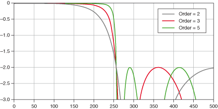
mystran wrote: Mon Jan 01, 2024 1:11 pm For Chebychev type 2, the chosen stopband ripple is your attenuation (ie. you can choose exactly -100dB or whatever) and the first zero of the filter is at cutoff (well, technically a bit above, but close enough that cutoff is at the chosen ripple), so it will always guarantee you the chosen attenuation above cutoff.. however the more attenuation you ask for, the wider the transition becomes and the earlier your passband reponse starts falling. This is a general theme that also occurs with elliptic and FIR filters too: for a given order there is a tradeoff between transition width and asking for more attenuation means accepting a wider transition.. or increasing the order.
Considering the shape of the Chebyshev 2…wait, this can't be right?

Image

...okay I'm just going to assume that graphic's wrong, multiplying the order 2 output by the order 3 output does not give the order 5 output shown, that can't be right, unless an order 2 outputting into an order 3 doesn't create an order 5 filter.

Is an order 5 Chebyshev stable? An order 5 filtering the output of an Order 3 looks interesting, along with potentially moving the cutoff point between the two filters, assuming that graphic is actually an accurate representation.

I also see Butterworths diagramed in terms of gain response, going to zero, rather than in terms of dB drop. Is that correct? If so, a higher order Butterworth seems more straightforward ("it's this steep and it goes to zero"), but potentially less optimal.

I also tested the Lazzarini-Timoney SVF a while back. Cutoff marked by a vertical line on the last chart. I lost the source file for this (dead SSD and no backups).
lazzarini-timoney.png
You do not have the required permissions to view the files attached to this post.
Last edited by jrmoserbaltimore on Mon Jan 01, 2024 3:58 pm, edited 1 time in total.

Post Reply

Return to “DSP and Plugin Development”