

justin3am's DIY eurorack adventure (complete!)
-
- KVRer
- 14 posts since 19 Nov, 2014
thanks for posting detailed pics and build reports. it helped me a lot. my only comment is that maybe you didn't need to have a case so big and deep. I built a doepfer style power supply with a torroidal transformer and it sits directly bellow the modules that are mostly skiff friendly even if they are DIY.
-

- KVRAF
- Topic Starter
- 12352 posts since 7 May, 2006 from Southern California
Hey thanks! I've seen you post in the DIY forum on Muff's right? You have a fuzz factory pcb for sale.
The cabinet could be slightly smaller but the Thomas White LPG and the j3rk fader are almost 100mm deep and the dual 291 I'm building now is even deeper.
Along the bottom there will be a 500mm touch ribbon. I'm working on a circuit based on Ian Fritz' design.
I suppose if I had built my own PSU, I could have saved some space but I have a bunch of these power-one supplies.
But yeah... It's big and heavy. It feels really sturdy though!
-
- KVRAF
- Topic Starter
- 12352 posts since 7 May, 2006 from Southern California
Almost done with the modules for this cabinet, just need to finish the dual J3rk 291.
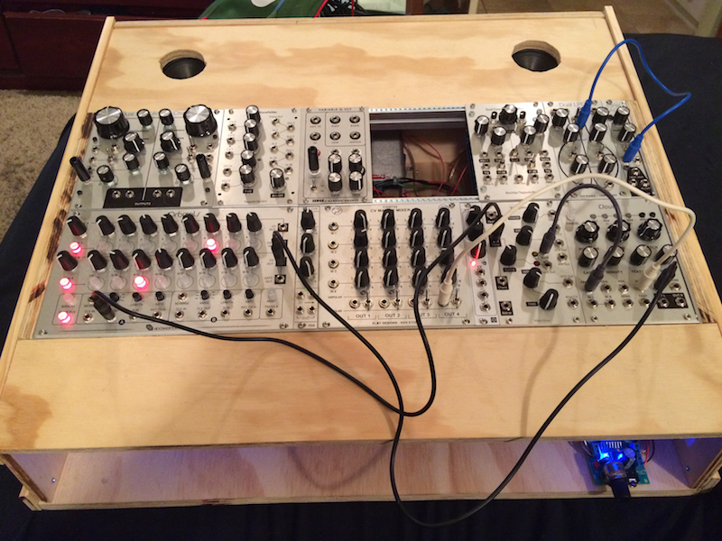
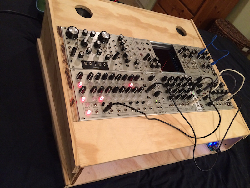
I hope to have the ribbon controller ready to test soon.
Here I'm just playing with Clouds w/ Parasite firmware in Resonator mode.
http://www.youtube.com/watch?v=nVdKuyksiGo
I hope to have the ribbon controller ready to test soon.
Here I'm just playing with Clouds w/ Parasite firmware in Resonator mode.
http://www.youtube.com/watch?v=nVdKuyksiGo
-

- Banned
- 10732 posts since 17 Nov, 2015
Yes... you should invest in a holesaw set, piece of cake.justin3am wrote:
I did the speaker holes in the top with my dremel tool and this attachment. The holes came out pretty janky...

If its being covered its not such a problem, but if you need to fit something into it....
-
- KVRAF
- Topic Starter
- 12352 posts since 7 May, 2006 from Southern California
Yes, there are a number of things I would have done differently now (and still may). I thought I would need a drill press to use a holesaw but it looks like they'd work with my cordless drill too.
I'm saving for a drill press now, so I can make some custom aluminum panels. I may redo the panel with the speaker holes, once I have that. I figure that once all the modules and electronic bits are done, then I will do the final finishing. It's easy enough to pull out all the synth parts, so I can do modifications to the cabinet.
I'm saving for a drill press now, so I can make some custom aluminum panels. I may redo the panel with the speaker holes, once I have that. I figure that once all the modules and electronic bits are done, then I will do the final finishing. It's easy enough to pull out all the synth parts, so I can do modifications to the cabinet.
-
- Banned
- 10732 posts since 17 Nov, 2015
Yeah they fit into a cordless drill (13mm chuck) and work well. Dont buy cheap ones tho, they really are crap and will just burn a wobbly hole thru the wood.
Ive used them on all sorts of timber, as well as aluminium and fiberglass.
Ive used them on all sorts of timber, as well as aluminium and fiberglass.
-
- KVRAF
- Topic Starter
- 12352 posts since 7 May, 2006 from Southern California
I'm working on a side project this weekend. I just received the parts, panels and PCBs for a pair of very interesting modules. 2 of each actually.
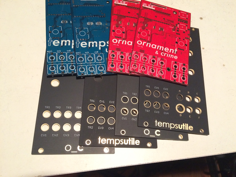
The hardware design and firmware for these modules are open source.
https://github.com/mxmxmx/O_C
https://github.com/mxmxmx/temps_utile-
They aren't available as kits. You can contact mxmxmx at the muffwiggler forum for PCBs and I got my Oscillisaurus front panels from Modular Addict. The boms in the github wiki pages list the parts needed for the build and in most cases the Mouser part numbers. Some parts are not available from mouser or just stupidly expensive. A Teensy from mouser is $25, so I got mine from eBay but they are also available from Oshpark. I also got my OLED displays from Ebay. The display comes in a few different formats. I originally bought a version which has the pins in a slightly different position from the intended part, so I had to order a new set.
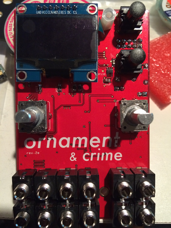
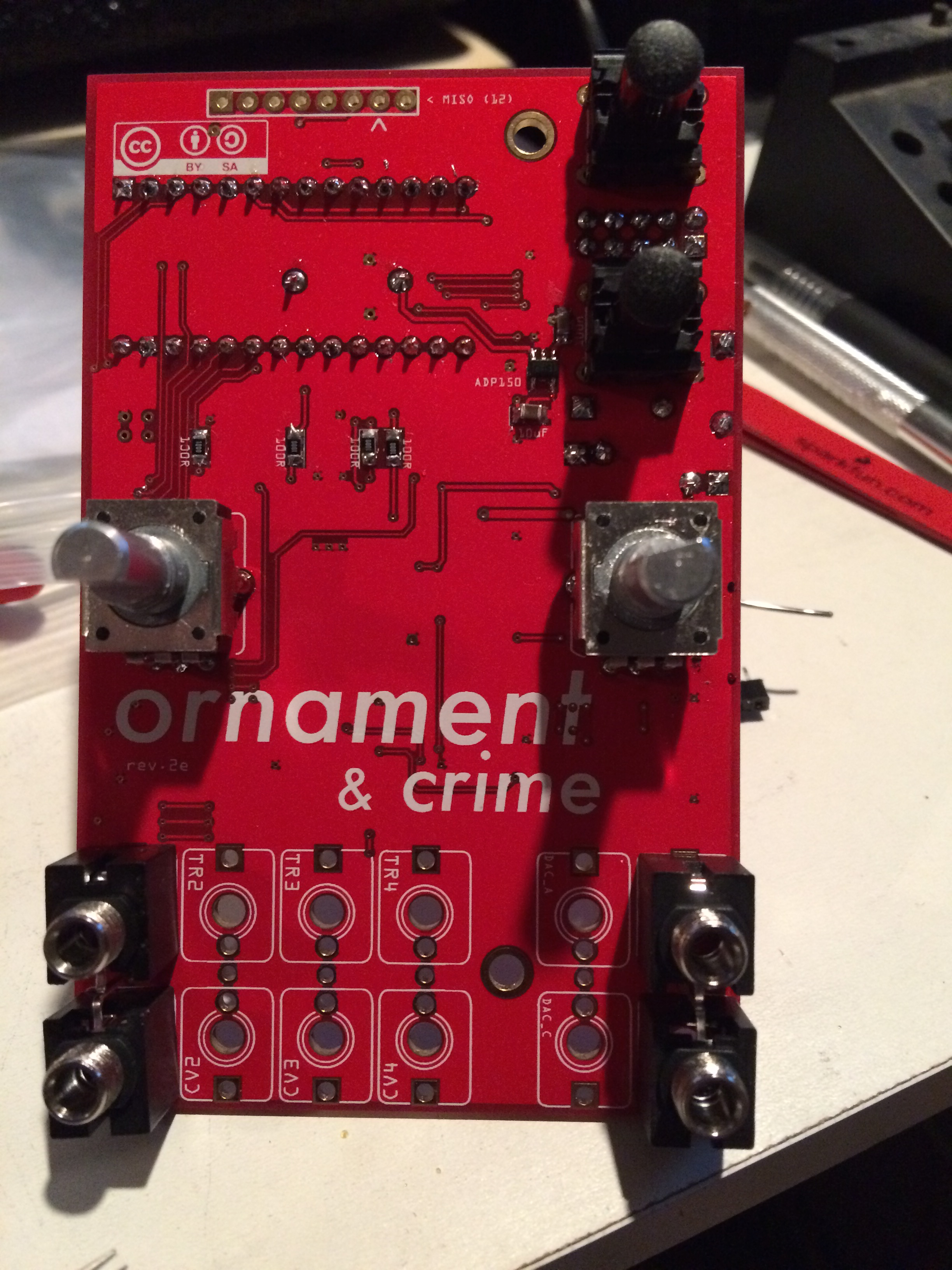
Ornaments + Crimes:
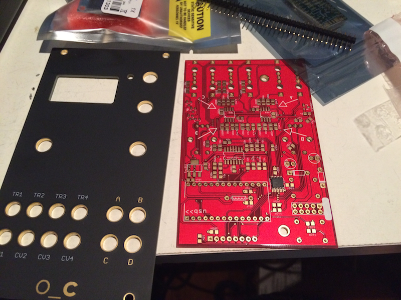
This module is a complex modulation source with 4 outputs, 4 CV inputs and 4 trigger inputs. Originally designed to function as a quantized analog shift register (ASR), it has since been expanded to include a number of different functions.
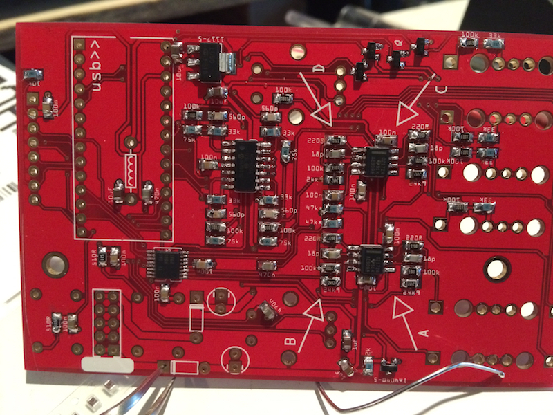
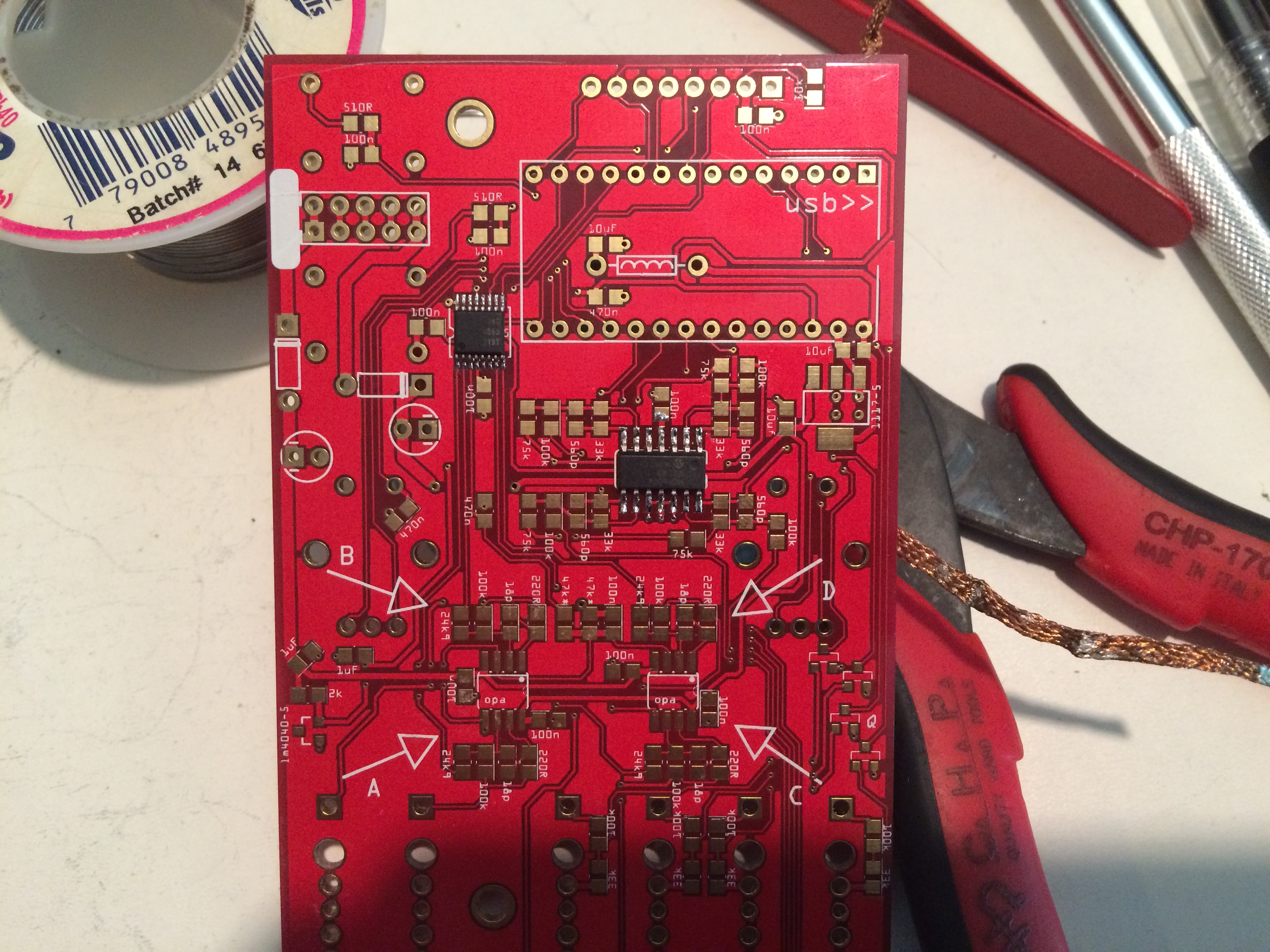
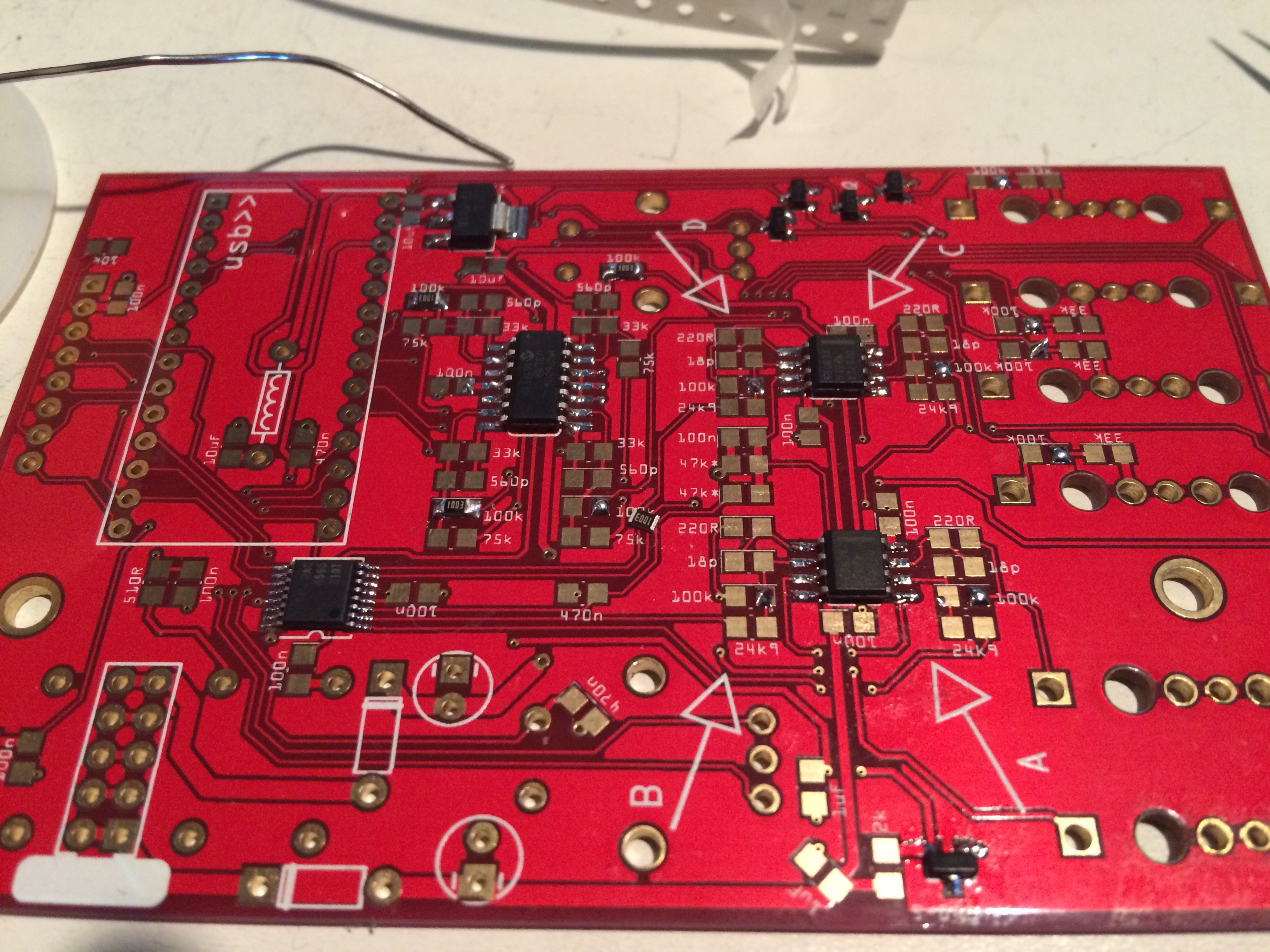
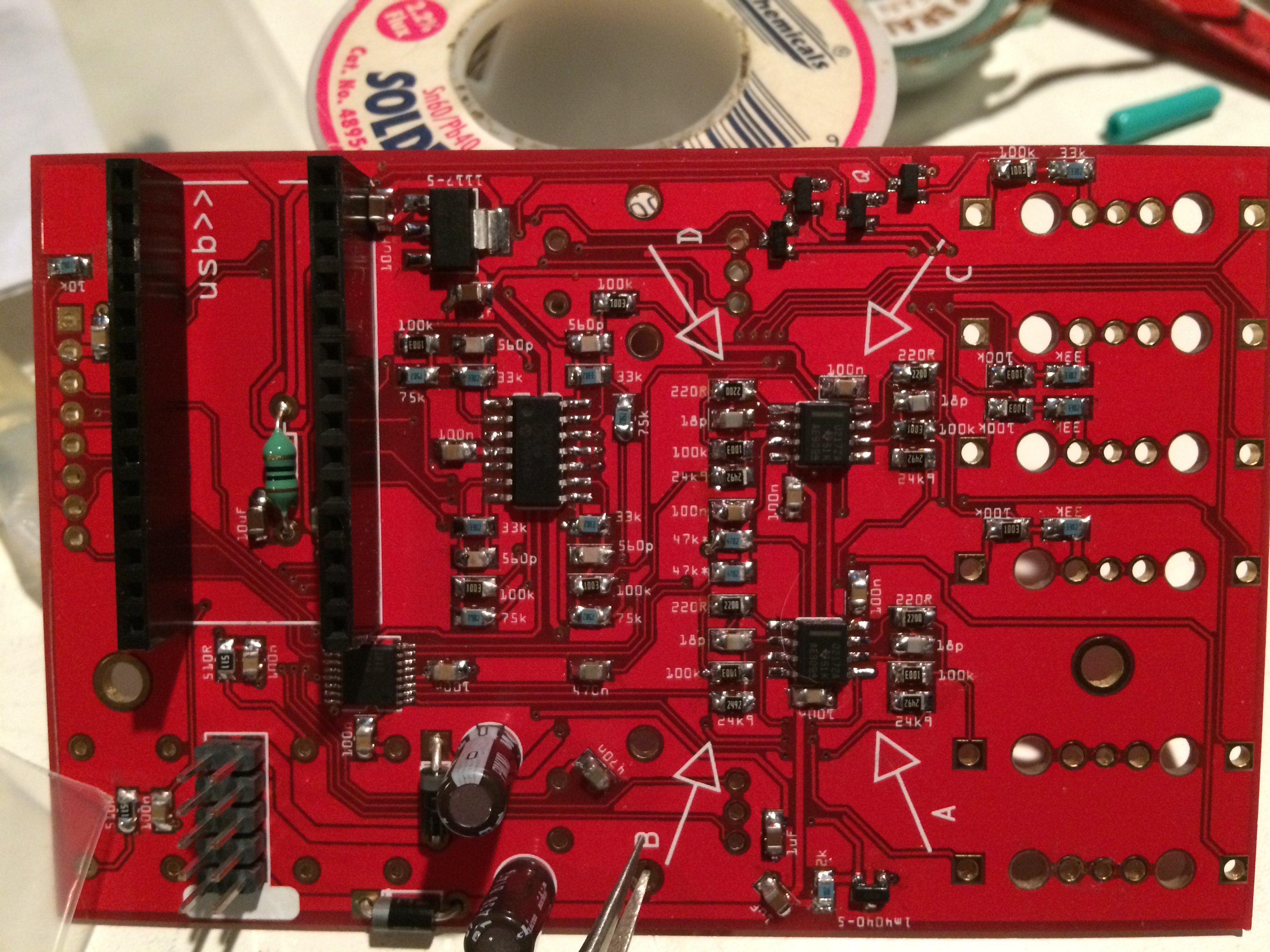
The components for this module are mostly 0805 SMT resistors and caps. There are a few fine pitch ICs and a hand full of through-hole parts. The front panel jacks and controls are all through-hole.
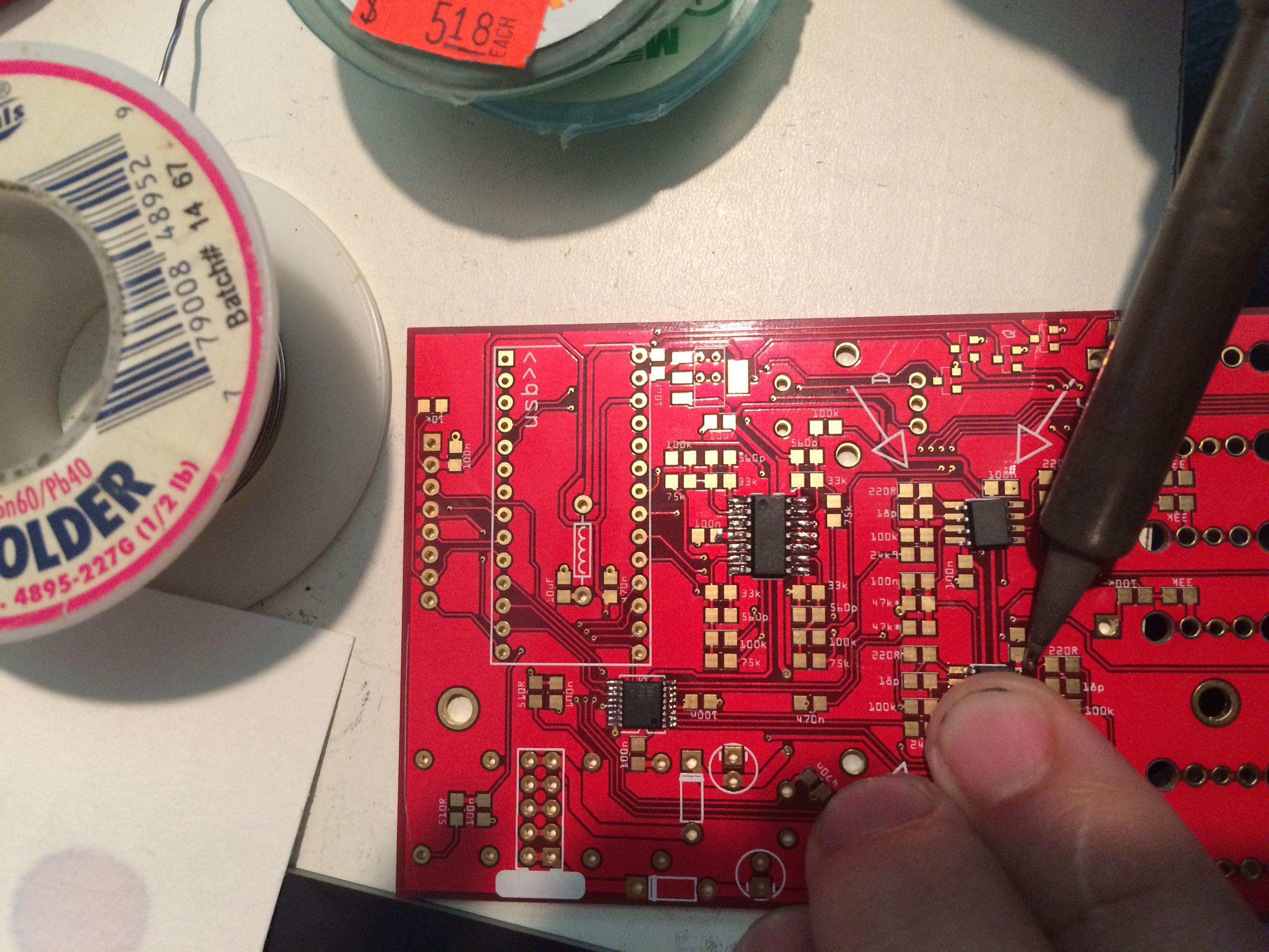
First I put liquid flux on the IC pads to help the solder flow.
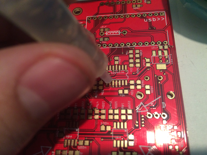
I start with the DAC (smaller) and the MCP6004 (larger).
[click for high-res]
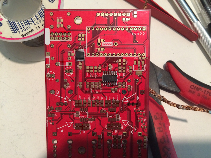
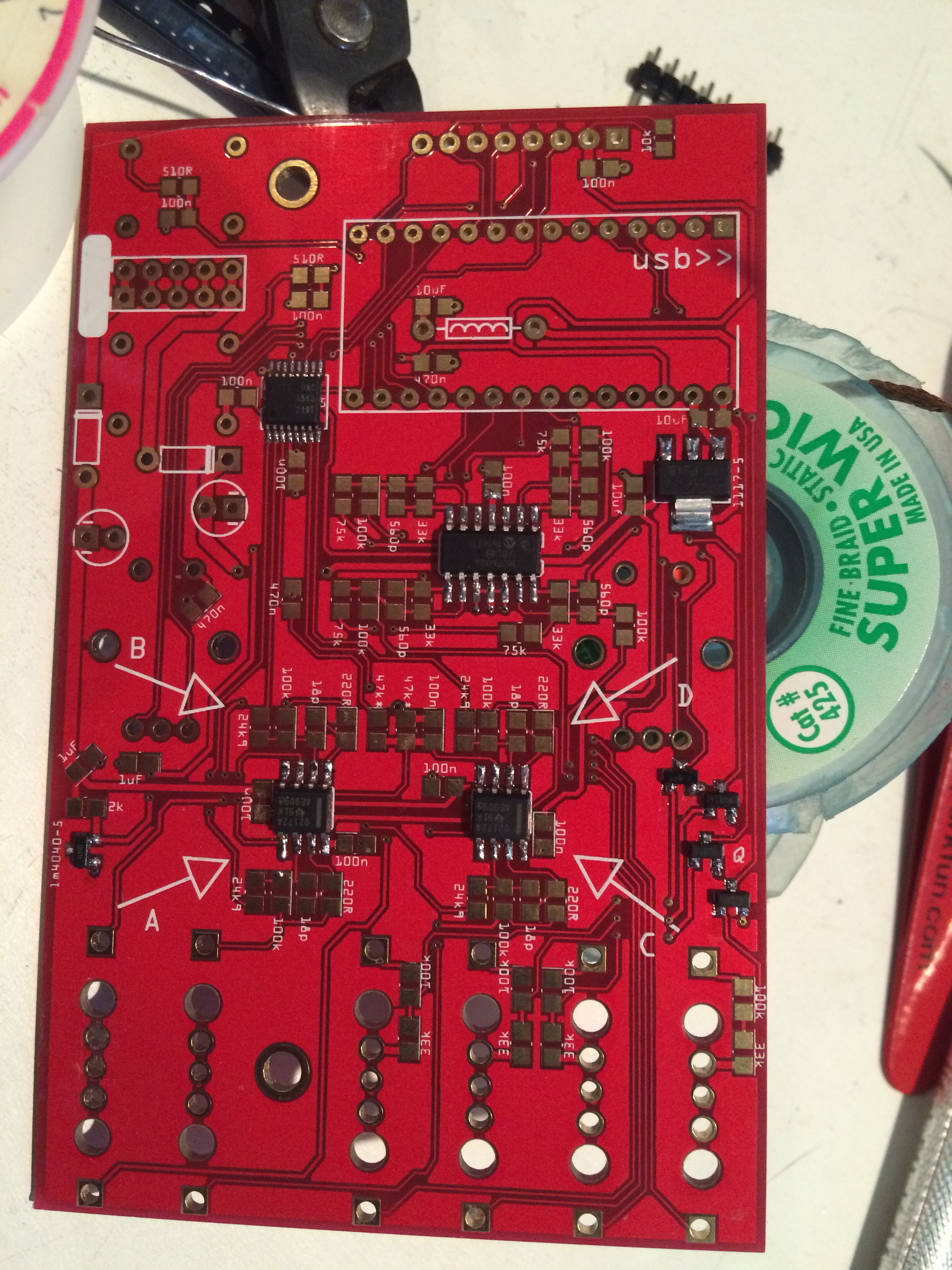
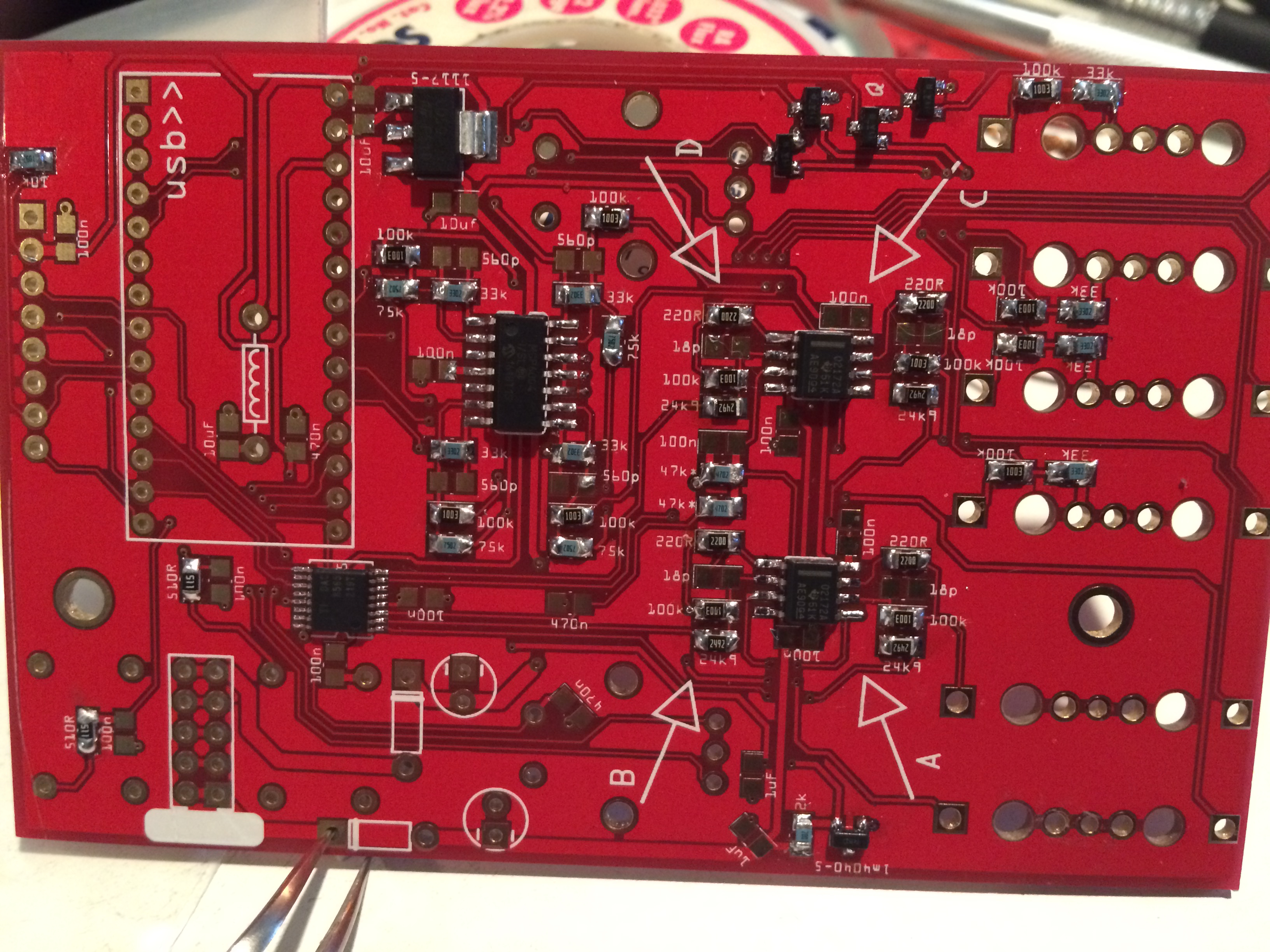
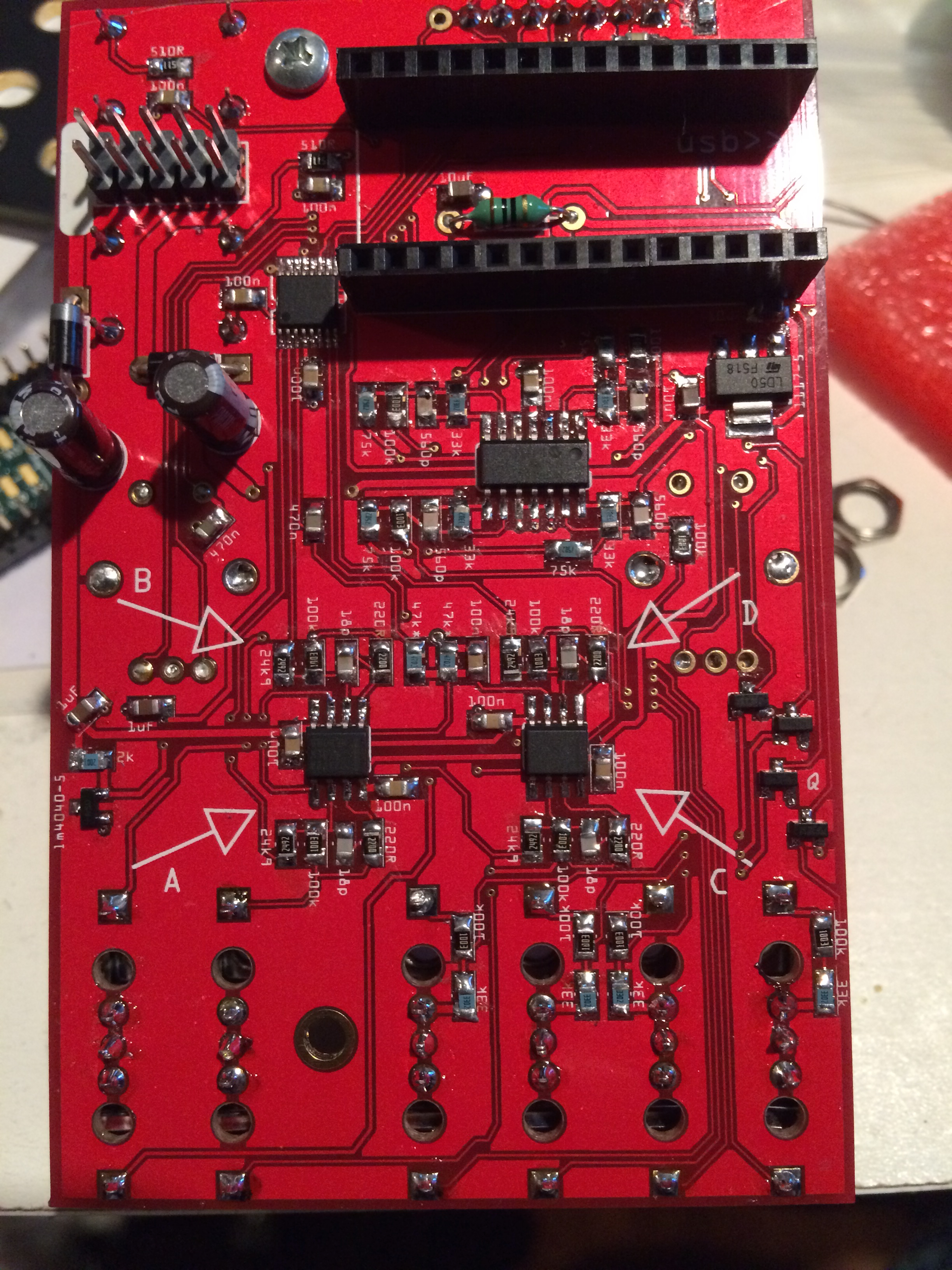
Then I do the OPAs.

If I needed to mount a chip with a TQFP package (like the MCU for Clouds) or QFN (like the stuff I build at work), I'd use a blade or beveled tip on my iron and apply solder paste. On this project, I just used a very fine tip and soldered each leg one at a time. No biggie, there are only a few legs per IC.
All the ICs done.
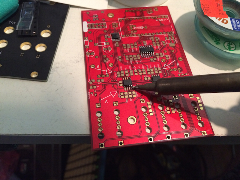
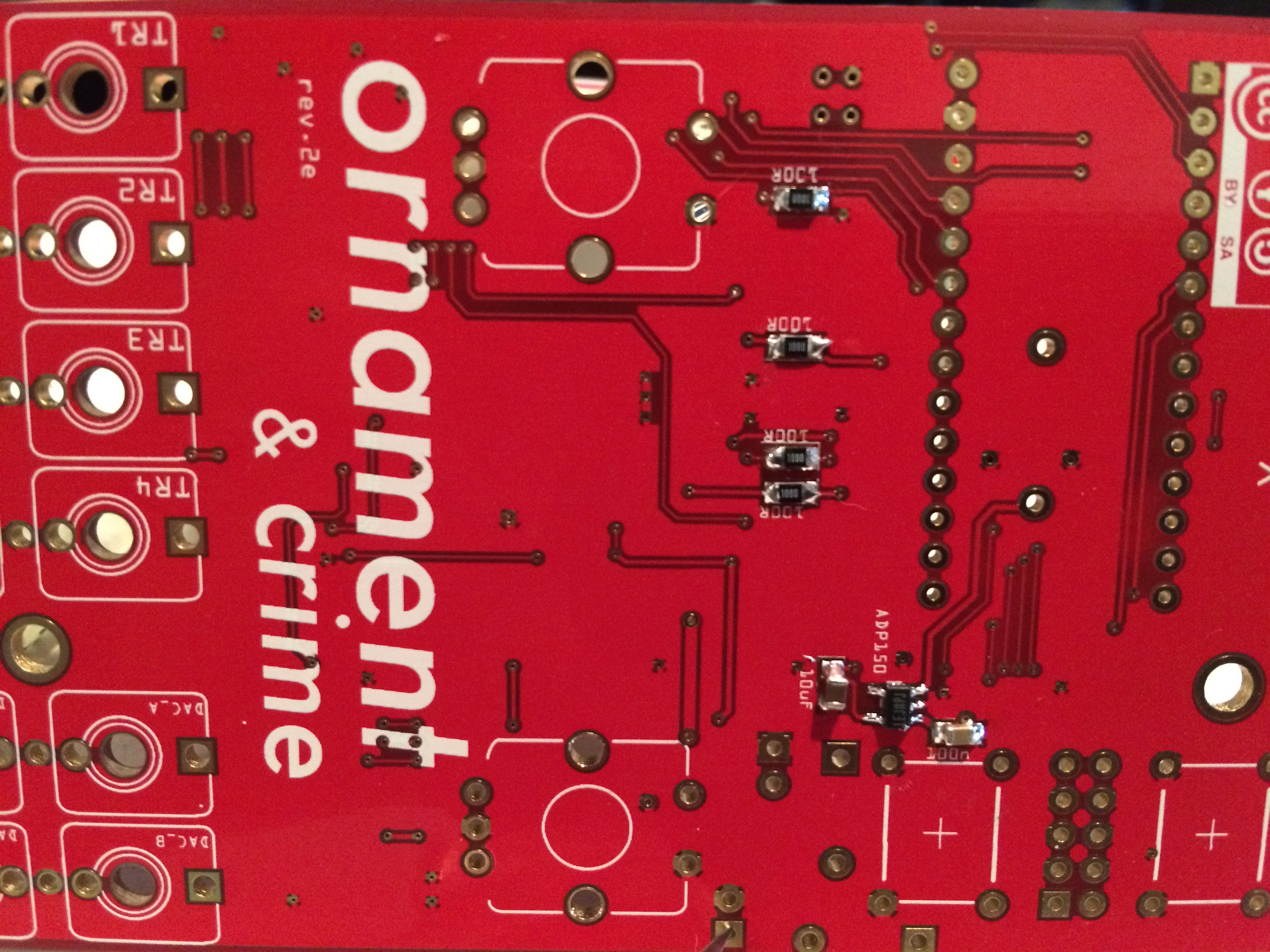
With the resistors and caps, I tin (or glob, really) one pad before placing the part.
See that one pad for each of the 100Ks has solder on them.

I then heat the solder on the one pad and place the resistor with a pair of angled tweezers. I lift the iron from the pad and the solder cools around the part, holding it in place. I can then solder the second pad. To get the solder to flow, it's important to touch the iron to the part and the pad. Make sure to use solder with a very small diameter, or else you'll want to go over every joint with solder wick, to avoid solder bridges.
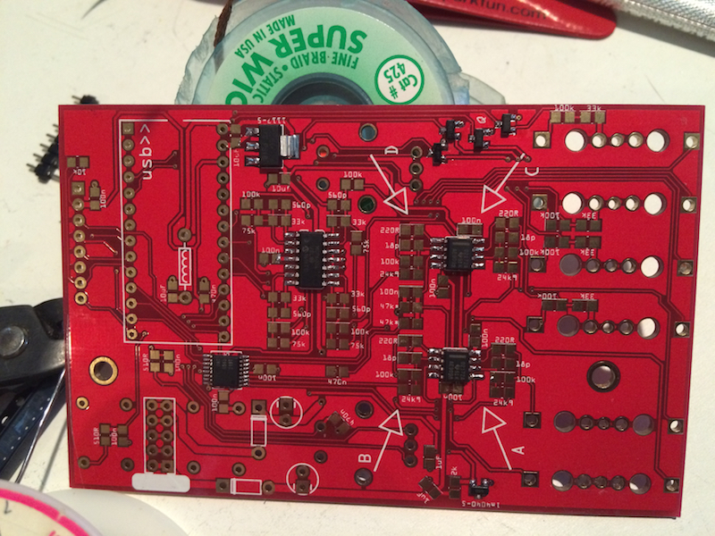
All of the resistors on the back done.

All the caps on the back done.
Now the parts on the front side.

Continued in the next post...
The hardware design and firmware for these modules are open source.
https://github.com/mxmxmx/O_C
https://github.com/mxmxmx/temps_utile-
They aren't available as kits. You can contact mxmxmx at the muffwiggler forum for PCBs and I got my Oscillisaurus front panels from Modular Addict. The boms in the github wiki pages list the parts needed for the build and in most cases the Mouser part numbers. Some parts are not available from mouser or just stupidly expensive. A Teensy from mouser is $25, so I got mine from eBay but they are also available from Oshpark. I also got my OLED displays from Ebay. The display comes in a few different formats. I originally bought a version which has the pins in a slightly different position from the intended part, so I had to order a new set.
Ornaments + Crimes:
This module is a complex modulation source with 4 outputs, 4 CV inputs and 4 trigger inputs. Originally designed to function as a quantized analog shift register (ASR), it has since been expanded to include a number of different functions.
The components for this module are mostly 0805 SMT resistors and caps. There are a few fine pitch ICs and a hand full of through-hole parts. The front panel jacks and controls are all through-hole.
First I put liquid flux on the IC pads to help the solder flow.
I start with the DAC (smaller) and the MCP6004 (larger).
[click for high-res]
Then I do the OPAs.
If I needed to mount a chip with a TQFP package (like the MCU for Clouds) or QFN (like the stuff I build at work), I'd use a blade or beveled tip on my iron and apply solder paste. On this project, I just used a very fine tip and soldered each leg one at a time. No biggie, there are only a few legs per IC.

All the ICs done.
With the resistors and caps, I tin (or glob, really) one pad before placing the part.
See that one pad for each of the 100Ks has solder on them.
I then heat the solder on the one pad and place the resistor with a pair of angled tweezers. I lift the iron from the pad and the solder cools around the part, holding it in place. I can then solder the second pad. To get the solder to flow, it's important to touch the iron to the part and the pad. Make sure to use solder with a very small diameter, or else you'll want to go over every joint with solder wick, to avoid solder bridges.
All of the resistors on the back done.
All the caps on the back done.

Now the parts on the front side.
Continued in the next post...
-
- KVRAF
- Topic Starter
- 12352 posts since 7 May, 2006 from Southern California
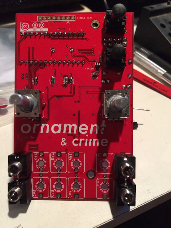
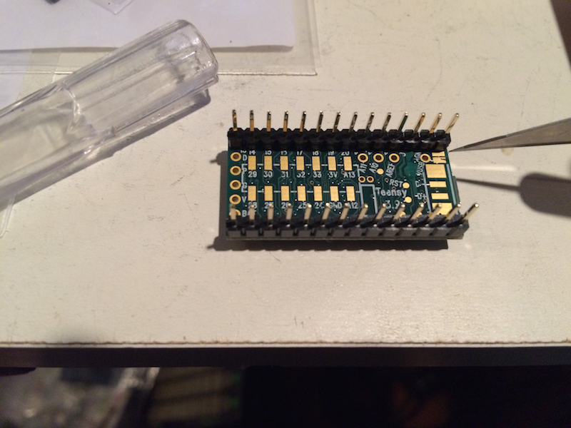
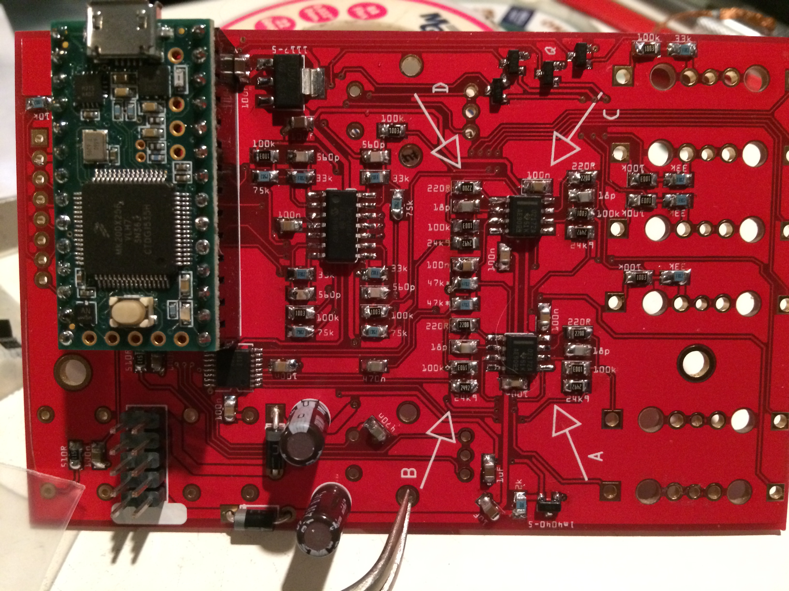
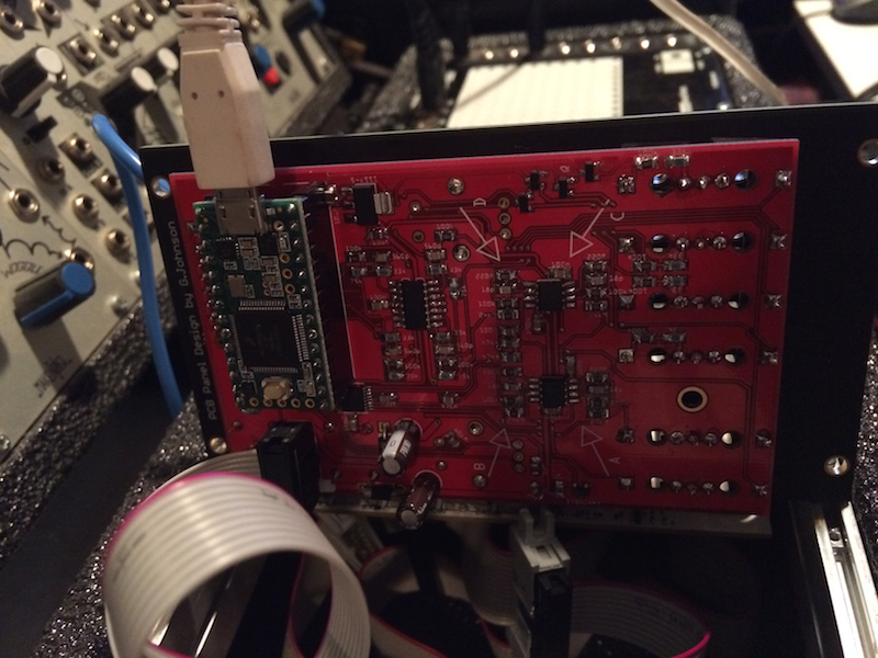
I had some single row headers to mount the Teensy but the guys on the muffwiggler forum recommend a low-profile header. I don't really care about the depth so much, so I just used the ones I have.

Installed the rest of the through-hole parts on the back side, as well.
Here it is with the Teensy.

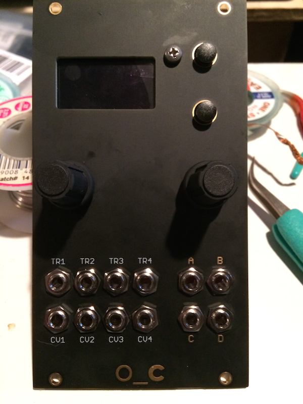
I started placing the front panel jacks and controls. I mounted the jacks to the panel to establish the panel height from the PCB. I then moved the encoders so that they're not flush with the PCB, rather the tops of the encoders line up with the jacks and the front panel.
Now all of the jacks are mounted and the display is mounted.
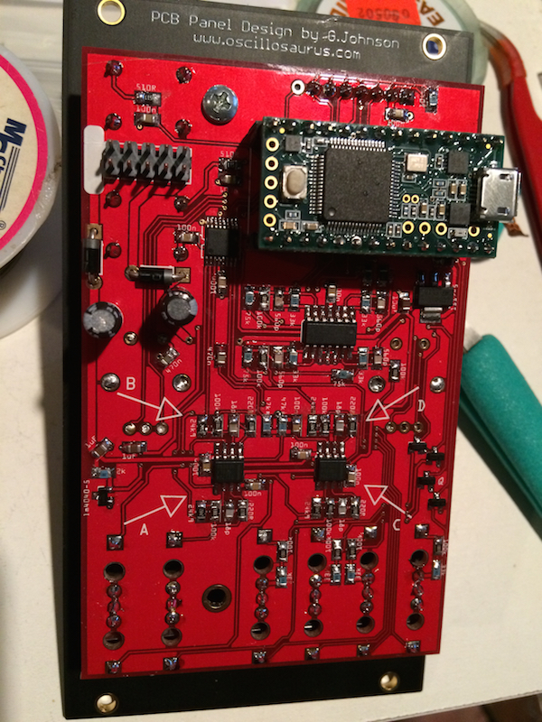
Here it is from behind.

As per the build instructions, I cut the trace on the Teensy which provides power from the USB port.
And now the front panel! Sexy!
Next comes the fun part!
Installed the rest of the through-hole parts on the back side, as well.
Here it is with the Teensy.
I started placing the front panel jacks and controls. I mounted the jacks to the panel to establish the panel height from the PCB. I then moved the encoders so that they're not flush with the PCB, rather the tops of the encoders line up with the jacks and the front panel.
Now all of the jacks are mounted and the display is mounted.
Here it is from behind.
As per the build instructions, I cut the trace on the Teensy which provides power from the USB port.
And now the front panel! Sexy!

Next comes the fun part!
-
- KVRAF
- Topic Starter
- 12352 posts since 7 May, 2006 from Southern California
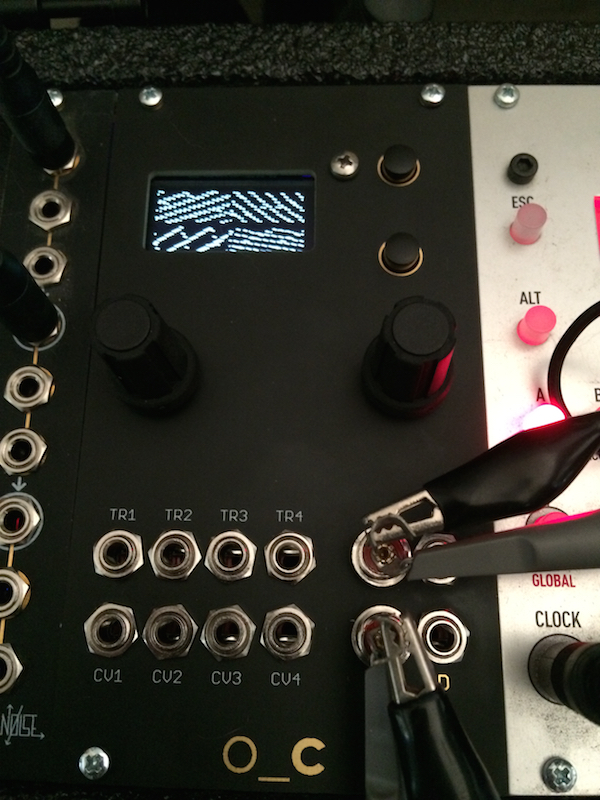
So now that assembly is complete, the module is ready for programming.
I downloaded the source code from the Github repository. I then installed the Teensy and ADC libraries for the Arduino IDE. The build instructions say that the board.txt file for the Teensy hardware library needs two lines modified in order to enable overclocking but that was already done in my case.
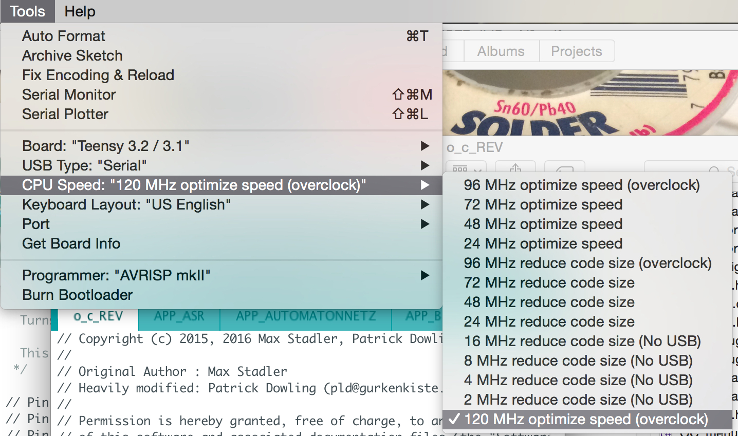
In the Arduino IDE I load the o_c_REV.ino file, then select the Teensy 3.2 hardware.
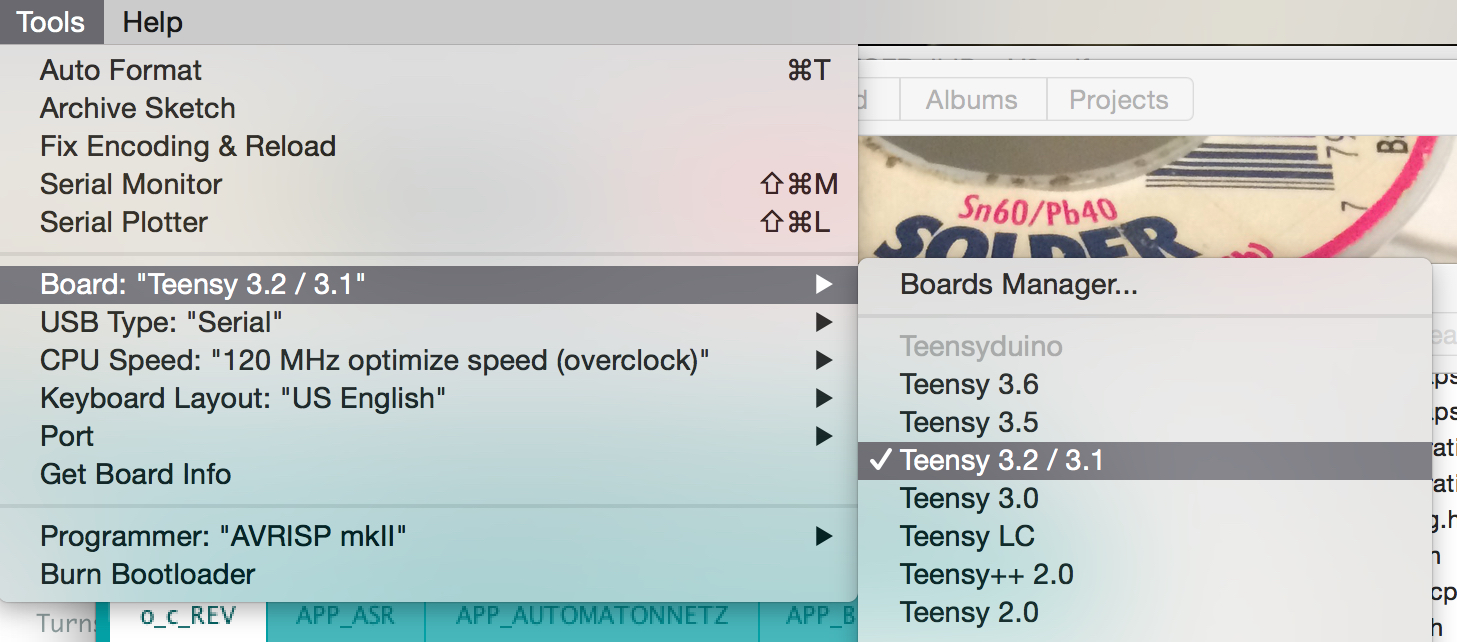
I set the clock speed for the processor.
The upload button compiles the code...
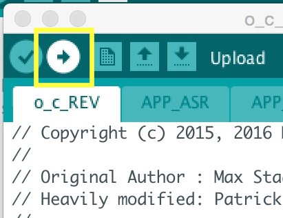
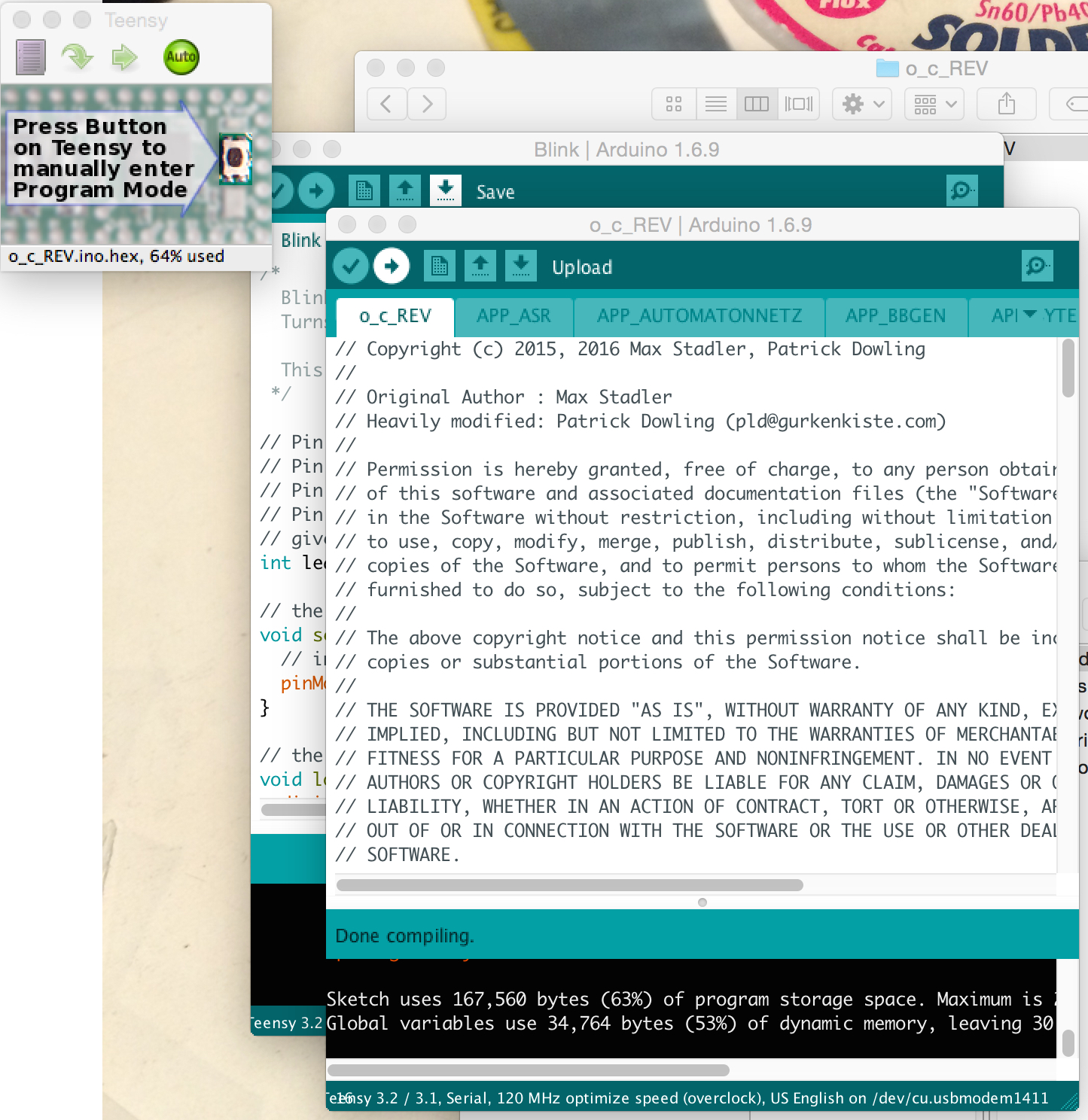
and sends it to the module.
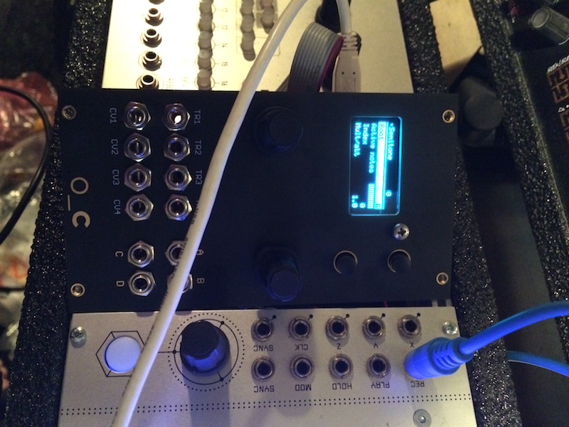
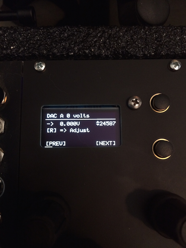
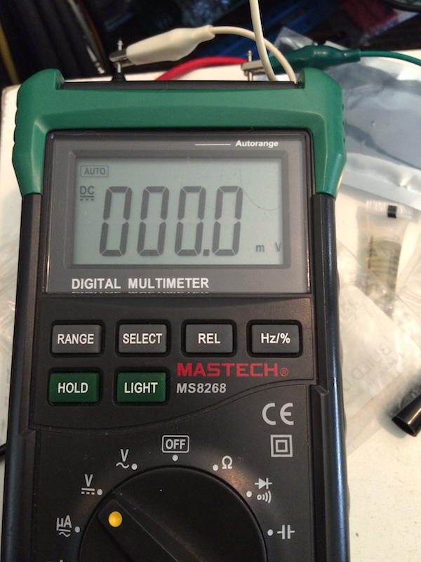
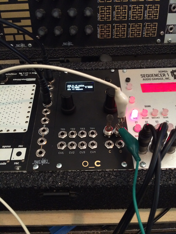
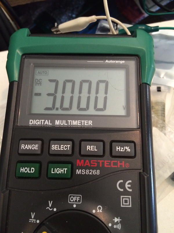
It's alive! Now it's time to calibrate. Each DAC output has a 10 offset points from -3v to +6v.
Each CV input has calibration settings too but I forgot to take pictures of that.
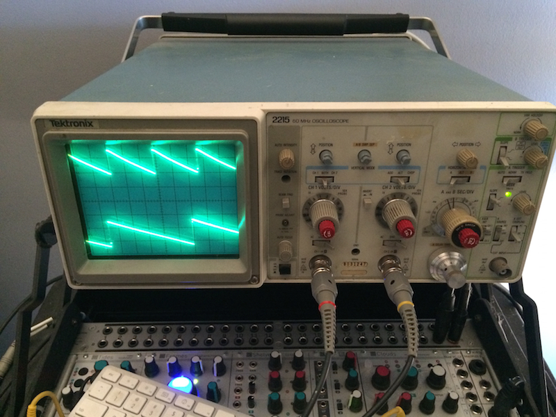
All done!
I downloaded the source code from the Github repository. I then installed the Teensy and ADC libraries for the Arduino IDE. The build instructions say that the board.txt file for the Teensy hardware library needs two lines modified in order to enable overclocking but that was already done in my case.
In the Arduino IDE I load the o_c_REV.ino file, then select the Teensy 3.2 hardware.
I set the clock speed for the processor.
The upload button compiles the code...
and sends it to the module.
It's alive! Now it's time to calibrate. Each DAC output has a 10 offset points from -3v to +6v.
Each CV input has calibration settings too but I forgot to take pictures of that.
All done!
-
- KVRAF
- Topic Starter
- 12352 posts since 7 May, 2006 from Southern California
I just finished this Dual VC Bandpass Filter.
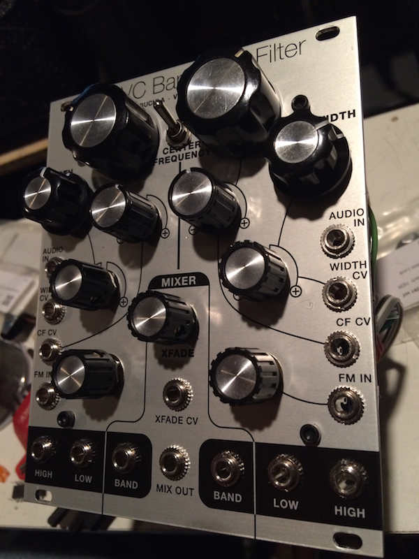
Based on the Buchla 291 each "bandpass" filter is actually a highpass filter and a lowpass filter in series, with a common set of controls. The Center Frequency controls the cutoff of both filters and the Width controls the relative frequency range between them. The Width also controls the resonance, so the resonance is high when the bandwidth is the smallest.
There are lowpass, highpass and bandpass outputs for each channel and a voltage controlled crossfader mixes the bandpass outputs from the two channels. It's a very flexible filter. It uses vactrols like a lowpass gate, so it's not really any good for audio rate modulation but the crossfader is prime for fast modulation.
I got the kit from Synthcube. The build instructions are very detailed and all of the parts were separated into little baggies, so it was a pretty easy build. However, there is a lot of panel wiring. Like a shitload.
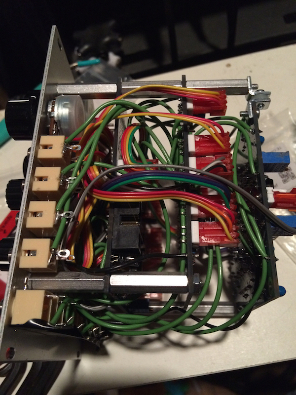
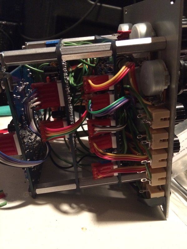
I added a 3PDT switch which changes the signal flow of the synth voice, so the filters can either be before or after the lowpass gate. I'll go into more detail about how the signals are routed between each of the filters, later.
Based on the Buchla 291 each "bandpass" filter is actually a highpass filter and a lowpass filter in series, with a common set of controls. The Center Frequency controls the cutoff of both filters and the Width controls the relative frequency range between them. The Width also controls the resonance, so the resonance is high when the bandwidth is the smallest.
There are lowpass, highpass and bandpass outputs for each channel and a voltage controlled crossfader mixes the bandpass outputs from the two channels. It's a very flexible filter. It uses vactrols like a lowpass gate, so it's not really any good for audio rate modulation but the crossfader is prime for fast modulation.
I got the kit from Synthcube. The build instructions are very detailed and all of the parts were separated into little baggies, so it was a pretty easy build. However, there is a lot of panel wiring. Like a shitload.
I added a 3PDT switch which changes the signal flow of the synth voice, so the filters can either be before or after the lowpass gate. I'll go into more detail about how the signals are routed between each of the filters, later.
-
- KVRAF
- Topic Starter
- 12352 posts since 7 May, 2006 from Southern California
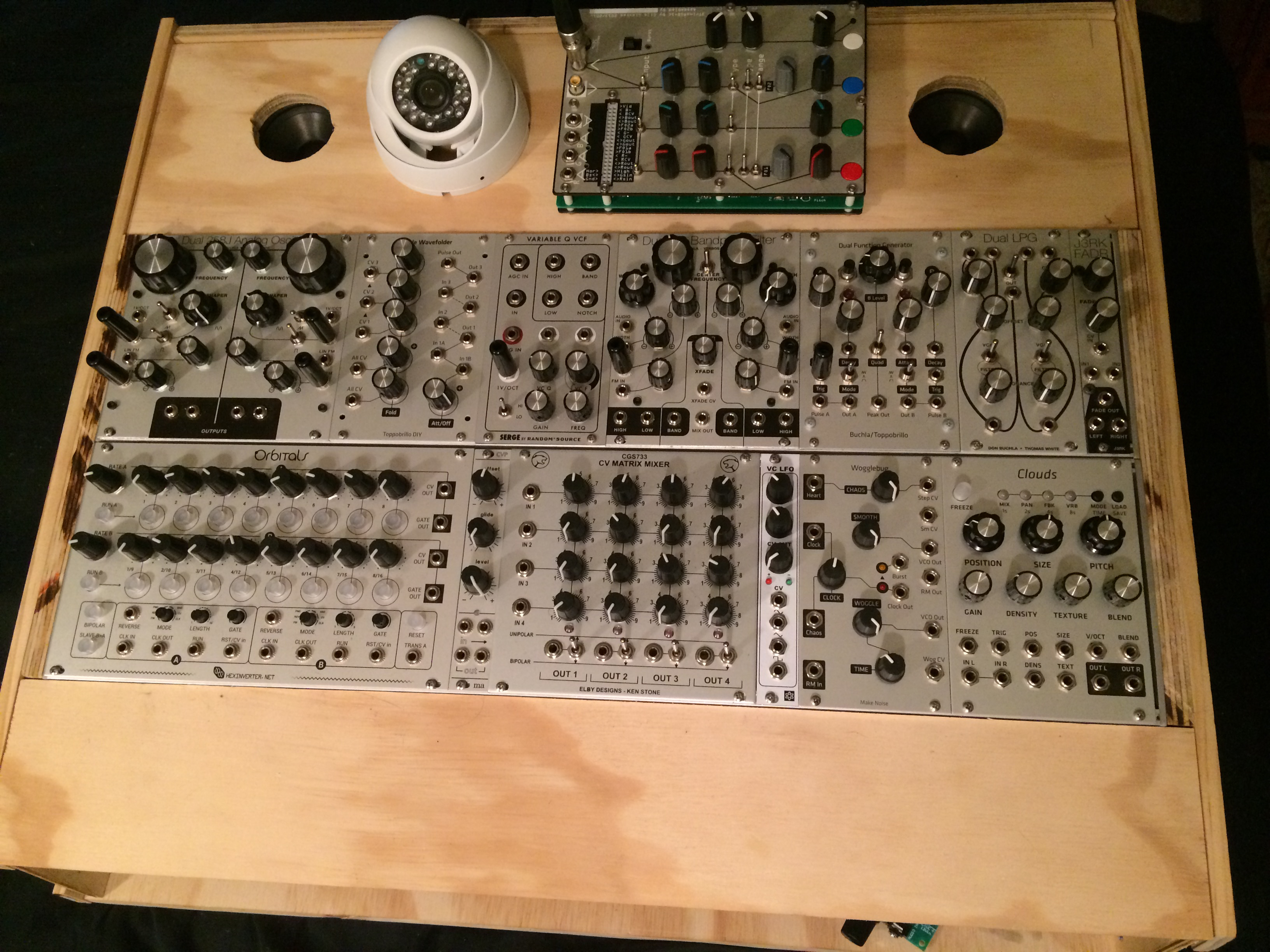
Now the main synth voice and modulation section are done.
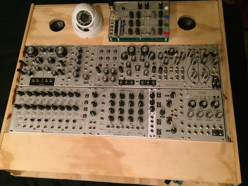
Click for more detail
The default routing has changed quite significantly since my original post.
The audio for the main synth voice, is routed as shown in this image:
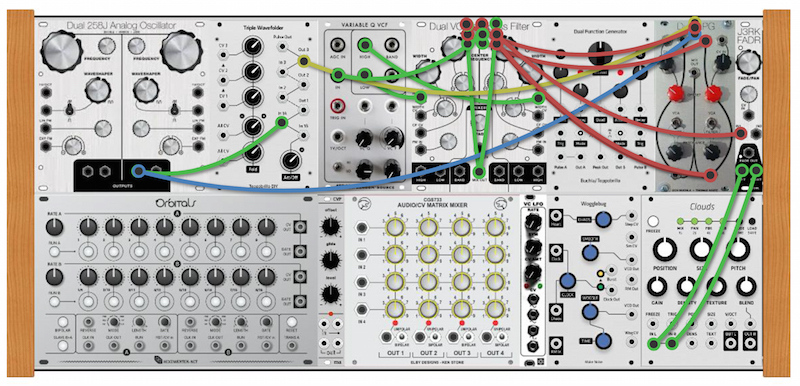
The output of oscillator 2 is routed to the input of the TWF and one side of a on-on switch. The other side of the switch is also connected to the output of oscillator 2. As a result, the switch acts as a bypass for the Triple Wavefolder. The output of the switch is connected to another switch (that rats nest of 9 connections in the middle of the Dual Bandpass Filter). The second switch makes puts the filters before or after channel 2 of the low pass gate.
The input of the VCFQ can either be output 3 of the Triple Wavefolder, the output of Oscillator 2 or the channel 2 output from the lowpass gate, depending on the positions of the two routing switches. The Lowpass output of the VCFQ is routed to channel 1 input of the Dual Bandpass Filter and the Highpass Output from the VCFQ goes to the channel 2 input of the Dual Bandpass Filter. With this configuration, the Cross Fader on the Dual Bandpass Filter acts as kind of a 'tone' control, when the 'Width' controls for the two filters are all the way open. The Cross Fader output of the Dual Bandpass Filter can be routed to the channel 2 input of the Lowpass Gate or the Input of the J3rk Fader/Panner.
Finally the L/R outputs of the J3rk Fader are routed the L/R inputs on Clouds.
This image shows the modulation routing:
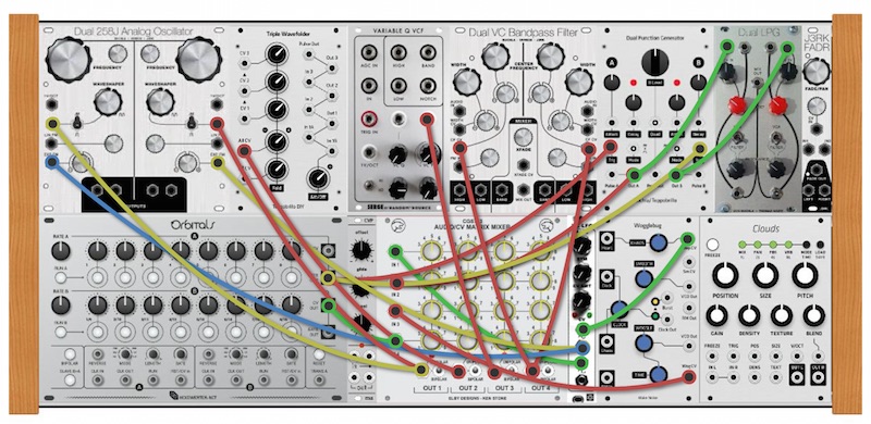
The hub of the modulation section is the CGS 4x4 Matrix mixer. Input 1 on the mixer is the Triangle Output of the VC LFO. Input 2 is connected to output A from the Dual Function generator. Input 3 is connected to the Woggle CV output from the Wogglebug. Input 4 is connected to the CV output from sequencer 2.
Output 1 of the Matrix mixer is routed to the Waveshaper CV inputs on each of the 258j oscillators. Output 2 is connected to the attenuated CV input on the Triple Wavefolder. Output 3 is connected to the Cutoff CV input on the VCFQ. Output 4 is connected to the Center Frequency CV inputs for both channels of the Dual Bandpass Filter.
The Channel A output of the Dual Function Generator (which is triggered by the Gate output of sequencer 1) is routed to the CV input for Channel 1 on the Lowpass Gate. Channel B of the Dual Function Generator (which is also triggered by the Gate output of sequencer 1) is routed to the CV input for Channel 2 on the Lowpass Gate.
The Sine output of the VCLFO is routed directly to the Exponential CV input for each oscillator on the Dual 258j.
The Stepped output on the Wogglebug is routed to the CV input on the VC LFO. The Smooth Output of the Wogglebug is routed to the 1v/Oct for Oscilltor 1 via a switch. More about that below.
This image shows the 1v/Oct routing:
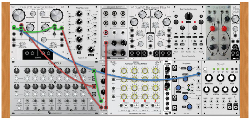
The CV output from sequencer 1 is routed to the Control Voltage Processor and the output of the CVP goes to the 1v/Oct inputs on the VCFQ and Oscillator 2 on the Dual 258j. There is a switch next to the Waveshaper control which links the 1v/Oct inputs for the two oscillators. There is another switch which connects either the CV output from sequencer 2 or the Smooth CV output from the Wogglebug. This connection is summed with the CV from sequencer 1, so you can offset the tuning of Osc1 in relationship to Osc2. With this setup, I can control the pitch of both oscillators and the VCFQ's cutoff, at the same time, via the Offset knob on the Control Voltage Processor.
Finally the FM routing:
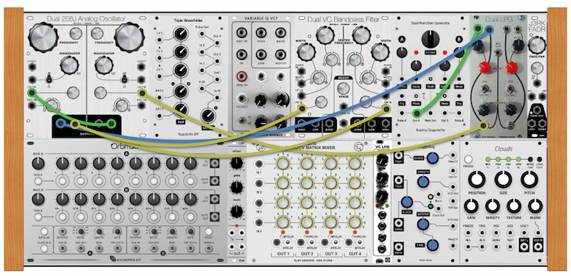
A hidden Triangle wave output from Oscillator 1 on the Dual 258j is connected to the channel 1 input of the Lowpass Gate. The output of that channel is connected to the Linear FM input for Oscillator 2. This allows for dynamic-depth FM with Osc1 as the modulator and Osc2 as the carrier. The channel A output from the Dual Function Generator controls the CV input for channel 1 on the Lowpass Gate. The output of Oscillator 2 is routed to the Linear FM input for Osc2, allowing cross modulation.
Click for more detail
The default routing has changed quite significantly since my original post.
The audio for the main synth voice, is routed as shown in this image:
The output of oscillator 2 is routed to the input of the TWF and one side of a on-on switch. The other side of the switch is also connected to the output of oscillator 2. As a result, the switch acts as a bypass for the Triple Wavefolder. The output of the switch is connected to another switch (that rats nest of 9 connections in the middle of the Dual Bandpass Filter). The second switch makes puts the filters before or after channel 2 of the low pass gate.
The input of the VCFQ can either be output 3 of the Triple Wavefolder, the output of Oscillator 2 or the channel 2 output from the lowpass gate, depending on the positions of the two routing switches. The Lowpass output of the VCFQ is routed to channel 1 input of the Dual Bandpass Filter and the Highpass Output from the VCFQ goes to the channel 2 input of the Dual Bandpass Filter. With this configuration, the Cross Fader on the Dual Bandpass Filter acts as kind of a 'tone' control, when the 'Width' controls for the two filters are all the way open. The Cross Fader output of the Dual Bandpass Filter can be routed to the channel 2 input of the Lowpass Gate or the Input of the J3rk Fader/Panner.
Finally the L/R outputs of the J3rk Fader are routed the L/R inputs on Clouds.
This image shows the modulation routing:
The hub of the modulation section is the CGS 4x4 Matrix mixer. Input 1 on the mixer is the Triangle Output of the VC LFO. Input 2 is connected to output A from the Dual Function generator. Input 3 is connected to the Woggle CV output from the Wogglebug. Input 4 is connected to the CV output from sequencer 2.
Output 1 of the Matrix mixer is routed to the Waveshaper CV inputs on each of the 258j oscillators. Output 2 is connected to the attenuated CV input on the Triple Wavefolder. Output 3 is connected to the Cutoff CV input on the VCFQ. Output 4 is connected to the Center Frequency CV inputs for both channels of the Dual Bandpass Filter.
The Channel A output of the Dual Function Generator (which is triggered by the Gate output of sequencer 1) is routed to the CV input for Channel 1 on the Lowpass Gate. Channel B of the Dual Function Generator (which is also triggered by the Gate output of sequencer 1) is routed to the CV input for Channel 2 on the Lowpass Gate.
The Sine output of the VCLFO is routed directly to the Exponential CV input for each oscillator on the Dual 258j.
The Stepped output on the Wogglebug is routed to the CV input on the VC LFO. The Smooth Output of the Wogglebug is routed to the 1v/Oct for Oscilltor 1 via a switch. More about that below.
This image shows the 1v/Oct routing:
The CV output from sequencer 1 is routed to the Control Voltage Processor and the output of the CVP goes to the 1v/Oct inputs on the VCFQ and Oscillator 2 on the Dual 258j. There is a switch next to the Waveshaper control which links the 1v/Oct inputs for the two oscillators. There is another switch which connects either the CV output from sequencer 2 or the Smooth CV output from the Wogglebug. This connection is summed with the CV from sequencer 1, so you can offset the tuning of Osc1 in relationship to Osc2. With this setup, I can control the pitch of both oscillators and the VCFQ's cutoff, at the same time, via the Offset knob on the Control Voltage Processor.
Finally the FM routing:
A hidden Triangle wave output from Oscillator 1 on the Dual 258j is connected to the channel 1 input of the Lowpass Gate. The output of that channel is connected to the Linear FM input for Oscillator 2. This allows for dynamic-depth FM with Osc1 as the modulator and Osc2 as the carrier. The channel A output from the Dual Function Generator controls the CV input for channel 1 on the Lowpass Gate. The output of Oscillator 2 is routed to the Linear FM input for Osc2, allowing cross modulation.
-

- KVRAF
- 7152 posts since 4 Apr, 2005 from here and there
-
- KVRAF
- Topic Starter
- 12352 posts since 7 May, 2006 from Southern California
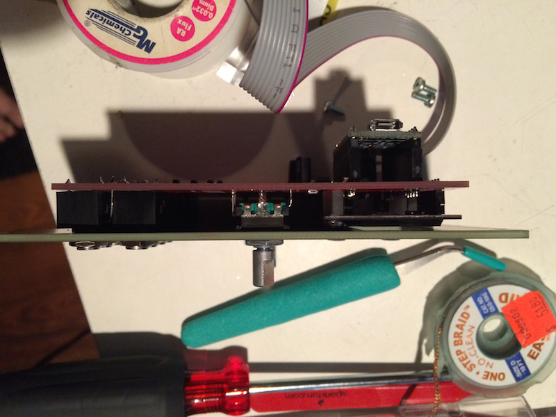
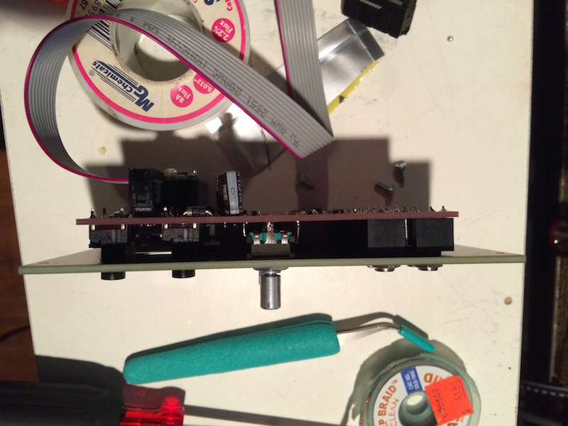
I finally found the time to finish the ribbon controller. It still needs some tweaks but I'm pretty happy with how it came out.
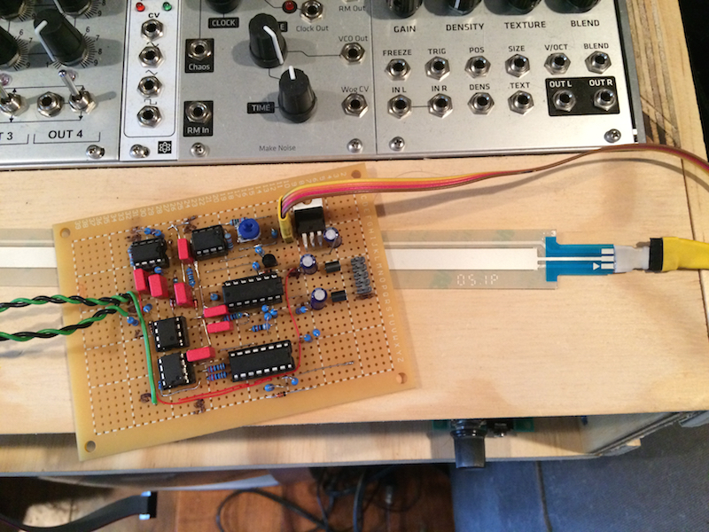
I built this, just from a schematic made by Ian Fritz. It uses a soft-pot touch sensor to generate a gate when the ribbon is touched and a control voltage based on position. The closer to the connector I touch, the higher the voltage. It's actually a bit of a complex circuit, as a track and hold is used to maintain the last position voltage when you remove your finger but still track the movement of your finger when you move it along the sensor.
It's all through hole parts I have to create my own board routing as there is no pre-fab circuit board available.
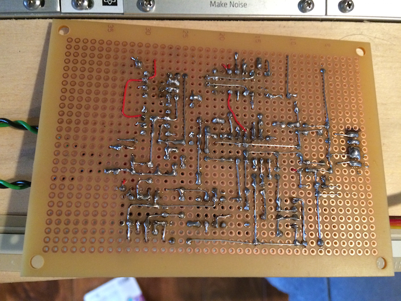
Luckily the schematic makes it easy to understand how it should go together. It powered up and worked on the first try!
https://www.youtube.com/watch?v=JPNuLWRA7rc
To be fair, I did a lot of testing throughout the build to make sure that everything was routed correctly. I'm in this dangerous place now, where I don't really have enough knowledge to warrant confidence but I've had enough successful builds, that I feel like I know what I'm doing...
I'll make a hole in the wood panel to feed the ribbon through and then I'll mount the circuit board to the bottom, side of the panel. I may also add circuitry for a pressure sensor and run an FSR underneath the position sensor.
But next, I think it's about time to start the finish of the cabinet.
I built this, just from a schematic made by Ian Fritz. It uses a soft-pot touch sensor to generate a gate when the ribbon is touched and a control voltage based on position. The closer to the connector I touch, the higher the voltage. It's actually a bit of a complex circuit, as a track and hold is used to maintain the last position voltage when you remove your finger but still track the movement of your finger when you move it along the sensor.
It's all through hole parts I have to create my own board routing as there is no pre-fab circuit board available.
Luckily the schematic makes it easy to understand how it should go together. It powered up and worked on the first try!
https://www.youtube.com/watch?v=JPNuLWRA7rc
To be fair, I did a lot of testing throughout the build to make sure that everything was routed correctly. I'm in this dangerous place now, where I don't really have enough knowledge to warrant confidence but I've had enough successful builds, that I feel like I know what I'm doing...
I'll make a hole in the wood panel to feed the ribbon through and then I'll mount the circuit board to the bottom, side of the panel. I may also add circuitry for a pressure sensor and run an FSR underneath the position sensor.
But next, I think it's about time to start the finish of the cabinet.
-
- KVRAF
- Topic Starter
- 12352 posts since 7 May, 2006 from Southern California
Oops, I just realized that I hadn't made the video public yet. 
-
- KVRAF
- 1869 posts since 21 Feb, 2004 from somewhere! anywhere!
I've also been experimenting with one of those spectrasymbol soft pots. I've got it connected to a very basic function generator circuit built around an LM324 op amp.
It's got me thinking to remove the aftertouch sensor strip from my axiom (another feature I never got on with) and find a new use for it.
Anyway, this thread is way beyond what I'm capable of - kind of like comparing NASA with the North Korean Space Program (up until they had a successful launch) - but very inspiring nonetheless.
Cheers
