justin3am's DIY eurorack adventure (complete!)

...and how to do so...
RELATED
PRODUCTS

Post

This will be the chronicle of my quest to build a monophonic synth with flexible architecture, based on DIY eurorack modules. :hihi:

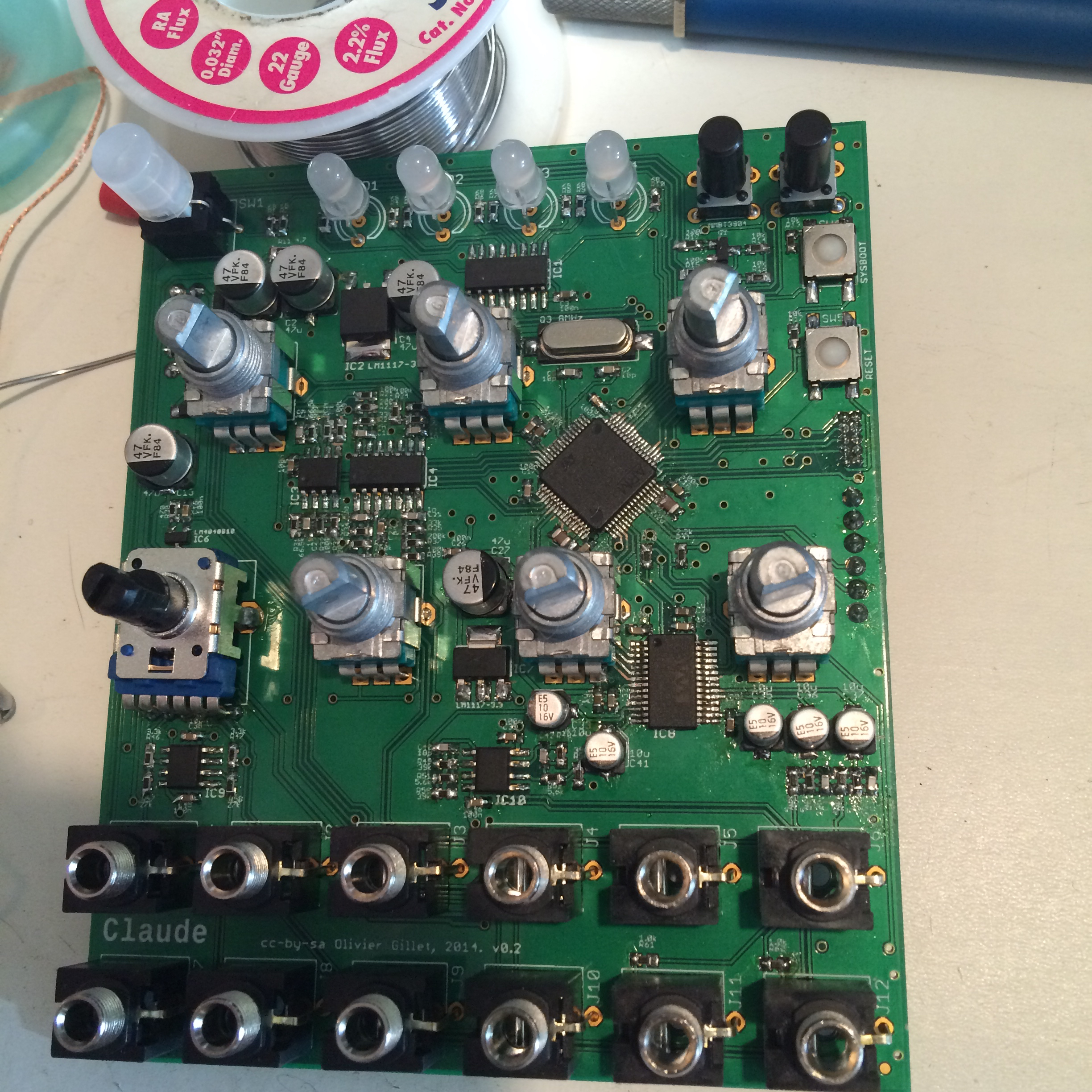
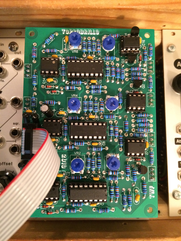
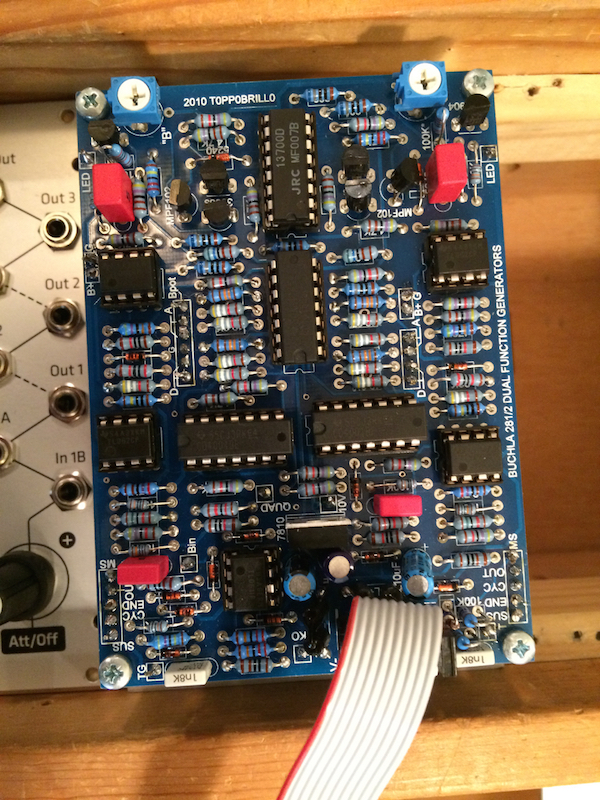
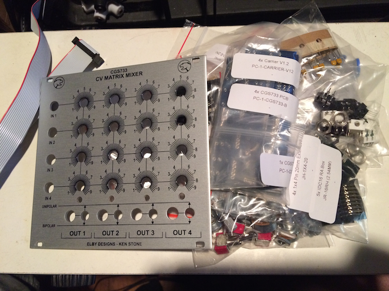
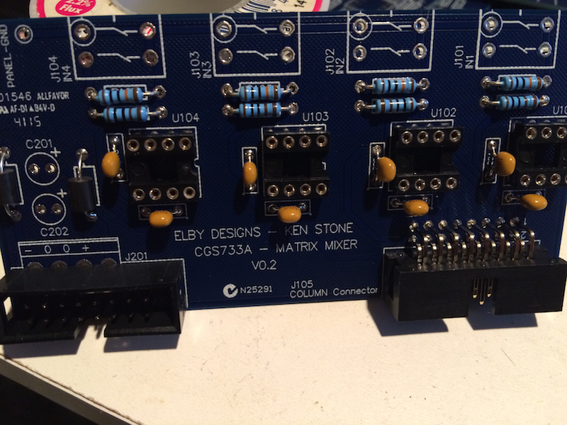
So far, this is what I have built:
Image
Image

Here is a recording of the first sounds:
http://www.youtube.com/watch?v=Z0aci5AkaiM

As you can see, minimal patch cables are required to make a very dynamic sound. Normalled connections route audio and modulation signals, so that connecting a patch cable to an input breaks the default routing. In other places, panel switches select between two default connections. The idea was heavily inspired by the Buchla Music Easel, Arp 2600 and Make Noise 0-Coast.

Later, I'll go into more detail about each module and the signal flow of the default patch. I should mention that there is a Make Noise Woggle Bug in there but that will go once I've built my own SOU type module.

This is a work in progress. I just cut some ply-wood to act as end-cheeks for the 108hp eurorack rails I'm using. In the end the cabinet will look similar but the whole thing will be enclosed, with built-in speakers and a touch ribbon along the front. I have some perforated aluminum I want to use... I have a lot of ideas but so far, nothing on paper.

Tonight was mostly about testing some speaker options. I got a cheap 2x10watt stereo amplifier from Amazon and scavenged speakers from broken console pianos. They sound pretty f**king terrible! But I found a set that have a shitty character that is endearing to me for some reason. Too big if I want to keep this thing portable, though. :(

It's been a fun project so far and I have enough left to do, to keep me busy for the next few months at least. :)

Post

Am I right in thinking a few of those modules have SMT components? I couldnae do that, I get flummoxed/annoyed enough with full-size bits.
my other modular synth is a bugbrand

Post

Yes, Clouds is mostly SMT. The Dual function generator has some 0804 caps. With the right tools and a little experience, I now find it easier to work with surface mount parts than through-hole. I use a stereo microscope at work but I just used a magnifier headset to build clouds. I learned how to do it by watching videos like this:
http://youtu.be/5uiroWBkdFY

With solder paste, liquid flux, a good pair of tweezers and a bevel or flat blade tip on your iron, it's much easier than you'd think. The solder just flows to the pads.

Post

What did you use for rails, and, do you know where I can find specific measurements for eurorack modules?

Post

Here are the mechanical specs, as defined by Doepfer... but I understand that it's largely based on europac sub-racks, without a back plane.

I got my rails from Pulp Logic. They are Vector Rails. I've also used Schroff rails. You can either put square sliding nuts in the channels or a threaded insert.

Post

Here are some more details about Clouds:
Image

If you didn't know, Clouds is a eurorack module from Mutable Instruments. A stereo DSP effect module primarily focused on granular delays and pitch shifting. The schematics, PCB design and firmware code for Clouds are available from the Mutable Instruments Github repository. So, not only can you build your own module, you can also hack the firmware, as others have done. I got my "Claude" PCB and panel from a group buy on the Muff Wiggler forum but you can also get them at Synth Cube.

There is a BOM in the Github repository. You can source most parts from Mouser but I got my pots from Tayda.

This was a fun project. I work with 0603 parts at work all the time, so assembly was't too difficult... following the maze of links in order to find all the necessary instructions to compile the firmware and load it into the module is another story.

Click for high-res.
Image
Image

Post

A little bit about the internal connections...

Here is an illustration of the audio signal flow:
Image
The output of the first oscillator (the modulator) is routed to the first channel of the lowpass gate. The output of the first LPG channel is then routed to the Linear FM input for the second oscillator (the carrier). This allows for dynamic depth FM between the two.

The output of the second oscillator has three destinations; the linear FM input for the the first oscillator (allowing for FM feedback), the input for the Triple Wave Folder and a switch on the second lowpass gate channel. The Output of the Triple Wave Folder is also connected to the the switch on the second LPG channel. This allows for switching between the unaltered output of the second oscillator and the wave-folded version. The switch has three positions, with the center position being off. Since the signal from this switch is mixed with the input jack, I can choose the default signal routing and also route a signal from another source into the same channel.

As of today, the output of the second LPG channel is routed to both of the inputs of the crossfader which makes it operate as a panner, when using the left/right outputs. The left and right outputs on the crossfader are routed the the left and right inputs on the Clouds module.

Here is an illustration of the modulation signal flow:
Image

The CV Output from the first channel of the sequencer is connected to a switch on the second oscillator. This switch sends CV to the 1v/oct input on the first oscillator. The CV output is always routed to the second oscillators 1v/oct input so the switch allows me to choose if the 1v/oct inputs for the two oscillators are linked.

The Gate Output from the first sequencer channel is routed to the trigger inputs for both of the functions generators (envelopes/lfos). The envelope is connected to the CV input for the first LPG channel (controlling the FM amount to the second oscillator). The second envelope is connected to the CV input for the second LPG channel (controlling the amount of signal to the cross fader).

The CV Output from the second sequencer channel and the smooth random output from the Woggle Bug are both connected to a switch on the first oscillator. The signal from this switch is mixed with the 1v/oct input jack. This allows me to offset the incoming CV (or the first sequencers cv, when linked with the second oscillator) with the second sequencer or a smoothly fluctuating random CV source. I used a three position switch, so I could turn that connection off, in the middle position.

I have a lot of additional connections planned once I complete the rest of the synth modules for this project.

Post

Here is another video, this one has better quality audio. Some nice bass sounds toward the end. The I'm over-doing it quite a bit with the FM, but the 258j just sounds so gnarly!
http://www.youtube.com/watch?v=WGvDdwC9 ... e=youtu.be

Post

This is the Dual 258j oscillator, from Stroh modular.
Image
It's based on the Buchla 258 dual oscillator. Two triangle core oscillators with variable waveshape and fantastic linear FM. For each oscillator you can choose between sawtooth and square wave output and the WAVESHAPER control crossfades between a sine-ish shape and the selected wave shape.

I have added a switch that links the 1v/oct input for the two oscillators and a switch with selects the source of the 1v/octave input for the first oscillator (sequencer2-off-wogglebug).

ImageImage

As you can see, the module is 2 of the same circuit board, mounted with hex standoffs. There is a TON of wiring! You can find the PCBs and panel at Synth Cube.

There are some hard to find parts. I was able to find them from various suppliers. The big polystyrene cap and other film caps I found at a local shop called All Electronics, I got the NTE129 transistor from Allied. Matching the resistors near the 4148 diodes is important to the symmetry of the oscillator wave shape but playing around with those resistor values or just trying different diodes, can have dramatic results. I added the output buffer mod to each oscillator to boost the output.

Here is a guide for the build from Thonk: 258j build instructions. More information about the circuit and mods can be found here: !!The Pseudo 0.5 258J Build/Mod Thread!!

Aside from wiring the jacks, switches and pots, it was a pretty simple build.

Post

Here is some information about the Toppobrillo Triple Wavefolder:
Image

The TWF is based on three identical saw>sine wave shapers. The design is inspired by the Serge TWS.
Toppobrillo wrote:about each folder: each stage can turn a sawtooth input into a really nice [much better than the old serge waveshaper] sine wave (bonus is that now you have cosine waves relative to the out of your VCO [quadrature]) , a triangle into a nearly perfect sine, and then fold these over into a nice soft clipping assymetrical waveform.

about CV distribution: each stage has a BIAS control which sets the initial bias for that stage. the ALL controls/ins provide apportioned CV to the 3 shapers to get a nice cascade of folds at the end of a series. a stages ALL CV is disabled when it's corresponding BIAS CV input is used.

about signal distribution: the folders are normalled in a series configuration, this connect is broken when plugging into the appropriate jack. stage 1 has 2 inputs, one with an attenuator which has a normalled DC bias. this is convenient for use as a 'symmetry' control, changing the harmonic spectra in the folds. stage 3 has an additional pulse output.

again, it is DC coupled throughout so it makes for some really amazing rhythmic modulation/ triggering when used with LF sources.

More info here.

Because of the way the wave shapers work, the TWF is very sensitive to dynamics and can create complex timbres from simple wave shapes. Using a more harmonically rich sound source can result in thick distortion or even dissonant ringmod like tones.

You can get the PCB for the TWF by itself and (as with most of the modules I've done) can be built for +/-12v or +/-15v power supplies, with minimal parts changes. The TWF is also available as a kit or an assembled module from several modular synth retailers. I built two different versions of the DIY TWF, one using a Manhattan Analog panel (which adds some additional features but also a lot of component wiring) and one using a Grayscale panel (shown in this post). The build documents can be found here: TWF DIY
Image

The benefit of the Grayscale panel, is that it can be used with the barcode panel PCB, so that all front panel jacks and pots are soldered to a PCB which connects to the main board via headers. This makes the build much easier than if all the jacks and controls need to be wired by hand.
Image

I'd say this was a very easy build and would recommend it for beginners. The only thing to watch out for is accidental solder bridges, since the parts are so close together.

Post

Some information about the Toppobrillo Dual Function Generator:
Image
This module consists of two voltage controllable envelopes (function generators) which act as a AD, ASR or cycling modes. It's half of a Buchla 281.

It's a very interesting module because it packs a lot of functionality in a small space. Each envelope can be an LFO, a triggered two-stage envelope (Attack>Decay) or a gated three-stage envelope (Attack>Sustain>Release). The Peak Out provides an OR comparison, using analog logic, of the two envelopes. This means that only the greater of the two signals will pass at any given time. With this output, you can get an ADSR by setting the env A to AD mode, the env B to ASR mode and using the B Level control as the sustain level.

The Quadrature mode causes each envelope to trigger the other at the end of it's Rise stage. This allows for some very complex modulations.

You can find more information here (including build documents, etc.): TOPPO 281

PCB and Panelcan be found at Synthcube.

For this module, I used the Grayscale Panel which matches the Grayscale panels for the TWF and Clouds, nicely. It's a pretty challenging build. The layout is dense and since there is no control PCB (not for this panel anyway), a lot of component wiring is required, in a small amount of space.

Image
Image

I added two momentary switches to the front panel. These connect 10v to the Trig inputs, so I can trigger the envelopes manually. Stupid, I put these switches too close to the B Level control. :dog: It's okay, though, they are short enough to not really be in the way. I added these because the cycling mode doesn't always trigger itself when you first activate it. Now, I've found it's really nice to be able to manually trigger the envelopes. To make sure that I'm not overloading the Trig inputs, I've created a basic gate combiner based on 4148 diodes. The circuit is based on this: OR-wired sockets

Post

It's been a while since I updated this thread... so here is the Random*Source EuroSerge Variable Q VCF I built recently.
Image

This build was pretty easy but I botched a solder joint on one of the THAT 2180's and spent the better part of a week troubleshooting that issue. :dog: :oops:
This is an incredible filter, I'll update this post with audio when I can. As you can see it has low pass, high pass, band pass and notch outputs. Pretty typical of a multi-mode filter. The AGC (automatic gain compensation) input adjust the gain relative to the resonance to control peaks. As the name implies, there is a CV input for the Q/resonance and the character of this filter's resonance is unique.

Another unusual feature is the Trig input. Without self-patching the VCFQ it will not oscillate when the resonance is turned up. However a trigger or fast envelope to the trigger input will "ping" the filter causing it to oscillate (or "ring"), decaying in volume after the initial impulse. The higher the resonance, the longer the decay. The decay has a very natural curve to it which is fantastic for creating tuned percussion sounds. With the Low/High switch set to low, pinging the filter results in decaying LFO-like modulations which would normally require an LFO with a reset input, a VCA and an AD envelope to achieve.

With the band pass output connected to the input, the filter will oscillate and low pass, high pass and notch outputs are shifted 90°, so it can be used as a quadrature oscillator. Again, with the Low/High switch set to Low, the VCFQ will work like a quadrature LFO (great for panning effects, with two VCAs!).

Image
I was surprised, including the PCBs, panel and the Mouser cart, this build only cost $135. This thing uses super high quality THAT VCAs and Burr-Brown op amps. I don't know how much that matters when the rest of the signal chain is made up of TL07Xs but whatev... Since there is a front panel PCB, there is no pot/jack wiring and everything goes together pretty easily. There is some ambiguity about which kind of caps to use. I just used C0G MLCCs everywhere except for the 22pf Micas (the big yellow guys), the 220pf styrenes (the silver can looking ones above the mica caps) and the electrolytics. Oh yeah, there's a 100nf poly film cap in there.

Post

In this video, I demonstrate the features and sound of the Random*Source VCFQ.
http://www.youtube.com/watch?v=9u8oIxeIkjo

Post

I built a 4x4 matrix mixer this weekend and took pictures of the process.

Image
So, a little background. This modules is a version of Ken Stone's Matrix Mixer. I built a Frac Rack version that I got from Bridchamber years ago. I sold that module and have missed it ever since.

I got this CGS733 CV Matrix Mixer kit from Elby in Australia. Here is a link to the build documentation. Shipping was pretty expensive and in retrospect, I should have just ordered the PCBs from CGS and source the parts from mouser. Oh well... I still enjoyed the build and it was nice to have all the parts in exact quantities and labeled.

Image

I started with the resistors and ferrites for the input board.
Image

Then the caps, IC sockets, and headers etc.
Image

I don't like the style of jacks which were included with the kit, so I used these thonkiconn jacks, that I got from synth cube.
Image
Since the footprint is not the same, I had to use leg clippings to connect the jacks to the pads. The jacks are panel mounted so they feel sturdy from the front panel but the board is not as secure as it would have been with the original jacks. I'm going to try to make a bracket for additional support.

Next, I populated each of the column PCBs, starting with the resistors.
Image

Diodes, caps, IC sockets, headers
Image

Installed the trimmers and ICs and mounted the front panel hardware.
Image

All column PCBs and input PCB mounted.
Image

All done.
Image

I'd say this was a pretty easy build. Would have been easier if I used the included jacks. ;) The build docs aren't very detailed. Just a BOM and some notes about assembly. The lowest pot in each column partially blocks the LED hole, so some creative engineering is required. Other than that, it was a straight forward process. Each board has few parts, so it's not as much work as it may appear.

Post

I made some good progress on the case this weekend.
Image
Image
Image

My wife says it looks "rustic". :hihi: I haven't done any wood work since I was a kid, so I'm proud. Lots of stuff still to be done... sanding, paint, etc. It's been a lot of fun!

I did the speaker holes in the top with my dremel tool and this attachment. The holes came out pretty janky but I plan to put an aluminum panel on top with all sorts of utility modules in that currently empty space. I'll be getting a drill press next month and I plan to drill small holes in the in patterns where the speaker holes are now.

Post Reply

Return to “DIY: Build it and they will come”