
Trying to wrap my head around using a delay line to create a Leslie-type vibrato.
First off, on a real Leslie, is the pitch highest as it approaches the listener/microphone (90 degrees before straight on)? Or when it's dead center in front of the listener/mic?
And then, where does that correlate to the sine wave that's modulating the delay time?

Leslie doppler effect
-

- KVRAF
- 15273 posts since 8 Mar, 2005 from Utrecht, Holland
The Doppler effect is the result of movement between the sound source and it's observer. When the rotating speaker is at the front, facing the listener/mic, then it moves perpendicular to that. So the pitch is then unchanged. Same situation when it is at the back. The pitch change (up or down) is highest right inbetween when it faces sideways.
If you look at the sine wave modulating the delay time, when it is at the top and bottom then the change in pitch is nearly zero because it doesn't go up or down (at that moment.) The biggest pitch change happens at the crossing of zero: there the angle is at its highest.
NB: if you build only that (a delay modulating the pitch with a sine wave) you don't yet have a very convincing Leslie effect. Because the rotating speaker is located inside a box, you also have to model the reflections inside that box. Also the Leslie has seperately moving horn and woofer with a cross-over splitting high and low frequencies. Extra complexity is that the rotating horn emits sound at both the front and the back.
See https://en.wikipedia.org/wiki/Leslie_speaker
We are the KVR collective. Resistance is futile. You will be assimilated. 
My MusicCalc is served over https!!
My MusicCalc is served over https!!
-
- KVRist
- Topic Starter
- 134 posts since 13 Apr, 2016
Thanks for the well written explanation. Now it makes sense that the pitch is at it's highest 90 degrees before it reaches front center. I was getting confused by every doppler example that uses a train going by, thinking that it was a left to right thing instead of a coming toward/moving away thing.
Certainly a cabinet and many more things go into the sound of a proper Leslie. I was just trying to understand the correlation between the physics of it all as I teach myself DSP.
Thanks again, Bert.
Certainly a cabinet and many more things go into the sound of a proper Leslie. I was just trying to understand the correlation between the physics of it all as I teach myself DSP.
Thanks again, Bert.
-
- KVRAF
- 3080 posts since 17 Apr, 2005 from S.E. TN
Not related directly to the pitch mod question, but was recently researching leslie emulators thinking maybe to buy one for mono live use. Haven't played live for awhile, had some gigs coming up.
Listening and reading, in addition to the nebulous cab resonance/reflection issue--
1. Pitch mod.
2. Amplitude mod.
3. Mic distance and possibly mic proximity effect.
4. Leslie amp distortion emulation
5. Mono compatibility
The leslie effect in my roland fa06 is supposedly the same as the VK organ leslie effect. Seems kinda cheez to me. Wondered if it really is the same they put in their dedicated organs? Yecch. Earlier auditioning on stereo studio monitors didn't sound so great, even less usable thru a mono live amp.
Main issue with the fa06 leslie effect especially in mono-- The low rotor amplitude mod is too drastic with no parameter to turn down the amplitude modulation. The low rotor amp mod is too "pulsating" too intense tremolo effect. But it does have decent low rotor pitch modulation at fast speed.
Some online leslie description/analysis claim the low rotor is mainly an amplitude/tremolo effect. That may be true for slow speed, but there is obviously noticeable pitch mod at fast speed. Just sayin, if you run across claims that low rotor is tremolo only, take it with a grain of salt. Any of the single-rotor leslies obviously have pitch mod at fast settings, and it works the same with the low drum of two-rotor models.
Dragged out my old motion sound model 3, which synthesizes the low rotor to drive an amp, and has a real treble rotor. It has a few opto phase shifter stages on the low rotor emulation but isn't very convincing. At fast speed the emulated low rotor has a bit of fast-speed pitch mod from the phase shifters, but IMO not enough. It is also "too intense amp mod" in mono. I'd probably tote the motion sound to the gig but was getting too much ground loop hum on the low rotor feed to the keyboard amp. Might try to debug that ground loop hum before the gig, and maybe by offset volume-balancing the two emulated low rotor outputs the extreme mono amplitude modulation could be tamed down.
Some of the commercial leslie emulators seem to offer control of that "too extreme amp mod" with a mic distance control. Obviously (if properly programmed) a mic distance emulation ought to diminish the amplitude modulation with greater distance. I think some of the commercial emulators alternately offer independent control of pitch mod vs amp mod. Some youtube demos of some of the emulators seem to illustrate that problem of "too much amplitude modulation" mostly for low rotor, but sometimes the horn rotor as well. And other emulators seem to have a better balance between pitch and amplitude modulation. Most youtube sound demos are in stereo, so mono compatibility would be hard to check, and the sound demos have variable-quality of course.
I never liked amp distortion on the real leslie tube amps. Distorted leslie tube amps would badly splatter the "fairly wimpy" stock 122/147 treble horn drivers. With a better stronger horn driver like the old EV 1829, the overdriven amp didn't abuse the driver so bad, but still sounded too nasty for me. Some of the emulators seem to offer fairly good "mellow" distortion without all that high end dirt. But some of them, a hammond tone with even slight added distortion sounds like white noise + ring modulation rather than usable distortion. Maybe some boxes just slavishly copy real vintage leslies, which sounded like dog doo to me when overdriven. Perhaps an acquired taste which I never acquired.
So after lots of tweaking I got the built-in FA06 leslie efect not sounding too terrible mono thru a keyboard amp. Will wait to see how that sounds on stage before buying a leslie emulator. Live cures many ills. Stuff that sounds awful thru studio speakers sometimes sounds fine on-stage.
For my own taste, if an emulator would offer adequate control over mono compatibility, speed, speed ramp, pitch and amp mod, I'd probably not worry about cabinet resonance/reflections. Distortion and cabinet emulation would be the last items on my priority list.
A couple of the modern hardware boxes sound pretty good in youtube demos, but expensive.
Various analog leslie emulators were made since the 1970's. Some of the early leslie emulators were based on phase shifter rather than delay line. Some of them didn't completely suck. Phase shifter plus perhaps a modulated first-order lowpass filter, MAY be as productive as a delay line for fast pitch modulation. A modulated gentle lowpass filter might give decent enough emulation of the timbre change, brighter when the horn/drum is facing listener, darker when horn/drum is facing away. And when modulated at fast rotor speed, the lowpass filter would contribute a little bit of pitch modulation.
The modulated phase shifter would add pitch vibrato at fast speed. Am guessing for leslie emulation, the wet/dry mix would be mostly wet to diminish the comb-filter effect. A little bit of comb-filtering might sound kinda like cabinet reflections, but too much comb filtering would sound like a phase shifter not a leslie. Probably there would be minimal phaser feedback resonance for this application.
A problem with my old Motion Sound horn-- It is too hifi. The high frequency response is too good. Hammonds are not high-frequency instruments and they don't sound right with harmonics much above 3 or 5 kHz. Some leslie emulators are similarly "too hifi". A better emulation of the real thing would roll off the highs.
Apologies the tedious message. Was just a topic recently on my mind.
-
- KVRian
- 653 posts since 4 Apr, 2010
Actually, one of the twin "horns" is a dummy, for balance. Only one side emits sound.BertKoor wrote:Extra complexity is that the rotating horn emits sound at both the front and the back.
My audio DSP blog: earlevel.com
-
- KVRAF
- 3080 posts since 17 Apr, 2005 from S.E. TN
One thing, dunno if any leslie emulators have this feature-- Maybe only my ear hears it thataway-- Real leslies, and most fake leslies I've heard, even most phasers or chorus that switch between fast and slow--
It is surely a psychoacoustic effect-- Fast speed sounds louder than slow speed.
Live I liked to footswitch control leslie speed. Playing piano with one hand, organ with the other. One foot on piano sustain pedal and the other foot switching between organ volume or leslie speed switch. Take foot off volume pedal to switch speeds, then sometimes the organ volume that seemed correct for slow speed, all of a sudden sounds too loud so I have to grab the organ pedal again and turn it down a bit.
Think I'll build a leslie speed switch onto the expression pedal but it would be nice if a leslie effect would have a volume tweak parameter so that the volume would get cut "just enough" a couple of dB or whatever it needs, so that fast and slow both sound to the ear the same amplitude level.
Maybe an easy way to add a speed switch to expression pedal-- Build a little plywood left-right swivel platform that the expression pedal can be velcro'd to. Maybe 20 degrees of swivel motion or whatever. Hook up a reed switch to the stationary part to route to a keyboard control switch input, and mount a magnet on the swiveling part. Might be less work than trying to figure out how to reliably mount a microswitch.
Some expression pedals have a toe-tab for leslie control (or other purposes) but are expensive and also the toe-tab pedals I've used were not convenient to use. Good idea in theory, not so great in practice for me.
-
- KVRist
- Topic Starter
- 134 posts since 13 Apr, 2016
Thanks for your very interesting thoughts, JCJR. Lots to think about, but one thing you got me wondering about is cabinet interaction. Besides the very obvious many reflections bouncing around everywhere, how does the wood and the size of the cabinet effect the sound? I would imagine that you could simulate the reflections with delay lines, but what about the resonance? If that's the proper word.
-
- KVRAF
- 3080 posts since 17 Apr, 2005 from S.E. TN
Hi Josh.joshb wrote:Thanks for your very interesting thoughts, JCJR. Lots to think about, but one thing you got me wondering about is cabinet interaction. Besides the very obvious many reflections bouncing around everywhere, how does the wood and the size of the cabinet effect the sound? I would imagine that you could simulate the reflections with delay lines, but what about the resonance? If that's the proper word.
There are regulars here more qualified to answer.
The cabinet for classic leslie 147 and 122 were fairly large and physically identical so far as I know. Everything was identical except amplifier details. The most notable difference between amplifiers was in the speed-switching circuitry (which ought not affect the sound). The 122 amp had balanced audio input less subject to hum. A couple of the modern expensive leslie emulators (including one from the new version of the leslie company) offer switch positions to choose between 122 and 147, with the 147 model brighter. Dunno what that's about. Maybe the 147 amp really was brighter or maybe the 147 model includes the tone contribution of that (rather awful sounding) expensive transistor floor-switch preamp which Leslie sold back then to drive a 147 via guitar or combo organ.
Anyway, I'm drifting off topic. There was also a 145 which was identical to a 147 except in a shorter cabinet. There was also an identical short model of a 122. Maybe it was numbered 125 or some other number, can't recall. In my neck of the woods 145's were fairly common but I didn't see many short 122's. Or maybe assumed they were 145's.
Basically the 122 amp was the best/easiest electronic match for a hammond B or C, and the 147 amp was easier to interface with combo organs and console organs not made by hammond. In fact, some of the hammond tone wheel organs with built-in amps and speakers such as L and M, were also easier to wire up to a 147.
The tall 122 and 147 had reputation of having more bass and mellower tone than the shorter but otherwise-identical models. Maybe that was true. Sometimes I wondered how much was placebo effect of having an even-bigger even-more-awkward to move cabinet. The short cabs were nearly the same weight, just took up less space in a truck. Neither were incredibly heavy, mostly just a very awkward shape to try to move around.
I did a lot of repair and mod work on leslies back then. Perhaps some generations varied, but the cabinets were built all bass-ackwards for a high fidelity speaker. As best I recall the side panels were typically about half inch plywood with beautiful hardwood veneer. Maybe some of the early models were built with solid wood or thicker wood, dunno. If you were gonna build a high-fidelity bass bin that size, even for modest volume level, you would at least use 3/4 inch plywood and probably use internal wood bracing to further suppress diaphragmatic cabinet resonances.
There was a bit of fluffy fiberglass damping inside the bass section but not very much. So it was a rather resonant wood box. For instance modern speaker design software assumes you are gonna build a stiff non-resonant box. I don't know if such software could model what happens when you build a big box out of thin material with minimal stiffening. The vibrating side panels possibly radiate a significant portion of the total SPL?
-
- KVRAF
- 3080 posts since 17 Apr, 2005 from S.E. TN
Folks usually try to "accurately" emulate linear speaker responses with FIR filter, using a recorded impulse response of the speaker. Equalizers have impulse responses, and impulse responses are equalizers. A grosser, less detailed emulation of a speaker response can be made by fine-tuning a collection of IIR filters. The more filters you add, potentially the better the emulation. A single lonely bandpass filter added to the dry signal to nail the most notable feature in the speaker response, might make an emulation sound more like the target than no filter at all. If you throw two bandpass filters at the TWO biggest features in the speaker response, might sound a little better than only one filter. Etc. At some point of slavishly trying to nail the speaker response, it would become more cpu efficient to simply compute one FIR rather than run all those parallel IIR filters.
The rotor cab reflections maybe could be done with a set of impulse response FIR filters? Or maybe it could be "close enough for rock'n'roll" to emulate the cab reflections with a multi-tapped short-delay line? To try to copy the geometry of the major 2 or 3 reflections between rotor and cab sides?
For a FIR emulation could be the question of what environment to measure the speaker in? Often in studios they will put absorbent gobos around the leslie to reduce room response or bleed, and just mic the leslie semi-anechoically. You could measure it that way in a studio. Or measure it elevated out-of-doors to get semi-anechoic impulse responses of the speaker itself. On the other hand, leslie really comes alive in a "fairly normal" untreated room. Not only the short time-delays of rotors moving in the cab, but longer time-delays of the rotors bouncing multiple times off all room surfaces. The ear hearing a delayed copy pitch shifted up from one wall, while also hearing a differently-delayed copy of pitch shifted down from some other wall.
But for a studio effect to use in a sequencer, maybe a "leslie in a live room" impulse response would be too "live". Maybe having so much room imprint that the leslie effect wouldn't be tweakable enough in a sequencer?
It is easy enough to take the back off a leslie. You can easily connect and disconnect the woofer and horn driver. You can easily slip off the belts so that the rotors don't turn, then easily put them back where they belong. For each test, you would want to replace the back panel however. Though some rock'n'rollers would remove the top, middle and bottom panels for routine performance. Seemed kinda weird to me, to run with the middle panel removed.
Anyway, you could place the leslie in whatever environment seems most likely of good results. Take off the belts and connect only the woofer. Use Room EQ Wizard or some other program to sine-sweep the woofer and get an impulse response. Get impulse responses with the rotor facing various directions. Maybe 4 measurements at 90 degree rotations or 8 measurements at 45 degree rotations or whatever. Then take off the back again, hook up only the horn, and repeat the multiple sweeps to get multiple impulse responses for various treble horn positions.
Then I suppose the leslie emulator code could crossfade between the different impulse responses while it is also doing the doppler modulation, amplitude modulation, and timbre modulation.
If alternately trying short tapped delay lines, someone smarter might do it better, but I'd probably sit down with pencil paper and drafting tools. Draw a simplified schematic of box and rotor. Draw various reflection paths between the rotor, box, and microphone at various rotation angles. Measure the distances to get the delay tap times.
Then run one or more tapped delay lines and crossfade between the taps along with the other rotation emulations. The "main" rotation emulation might have only pitch mod, am not certain. Then run thru the crossfaded tapped delays and mix only a portion of the delay with the pitch mod original signal. And then add the amplitude and timbre modulation?
Alternately, maybe it would be more natural to do all the other effects, Pitch modulation, Amplitude modulation, Timbre modulation, before feeding the crossfaded delay line, and then mix part of the delay line output with the "main" pitch+amp+timbre output?
Just some ideas, maybe not so workable.
-
- KVRist
- Topic Starter
- 134 posts since 13 Apr, 2016
Thanks so much for your thoughts and insight, JCJR.
The latest thing I've been playing with (and not satisfied with) is the amplitude modulation part of the leslie sound. Especially as it relates to microphone distance.
The obvious technique would be to modulate the amplitude with a sine wave, maybe a deeper sine wave for more modulation when the microphone is closer, and less when the microphone is further away.
But that doesn't seem enough to me. What my ears perceive is that when the microphone is very close to the rotating horn, the sound is very loud for a very short time when the horn straight at the microphone and falls off rapidly for the rest of the rotation. To visualize, it would be like the peak of the sine wave used to modulate would be much narrower/sharper than the valley part. But only when the mic is very close. And it seems like that modulation wave would be closer to a proper sine wave when the mic is further away. Does that make sense?
If so, what am I hearing and how would I put that into an algorithm?
My assumptions are that the horn has a radius of about 10 inches, so when the mic is placed close, the distance between the mic and horn goes between 6 inches and 26 inches, and when the mic is further away, the distance goes between 42 inches and 62 inches.
It just doesn't seem to my ears like a simple sine wave modulation.
-
- KVRAF
- 3080 posts since 17 Apr, 2005 from S.E. TN
I was thinking more about it after our last messages. In the previous messages I was "mixing up" confused thoughts about "quick and dirty" emulation on the one hand, versus "physical model" emulation on the other. I suppose there would be a variety of approaches between "quick and dirty" versus an accurate physical model. Depending on how much of a science project one wishes to make it.
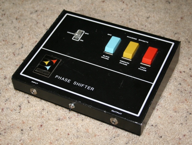
The maestro PS-1 was one of Oberheim's first commercial designs. It was an early implementation of a phase shifter, with an "acceleration" feature that would slowly ramp up or down the speed. A couple of years later Boss/Roland sold a similar phase shifter stomp box with a fast/slow speed ramp feature. They did not sound like leslies, but sounded more like leslies than some of the poorer-sounding, later-design "leslie emulators".
Back then sometimes I'd run that PS-1 or the later Roland/Boss phaser into an actual leslie. Switch both the phaser plus leslie fast/slow. Sometimes switch speed of both simultaneously. Sometimes switch em out-of-sequence, speed one up before speeding the other up, or vice-versa. Seemed to sound purt good at the time but perhaps if I heard it today it would sound unbearably tasteless. Phaser + leslie could almost make you dizzy.
http://www.wingspreadrecords.com/maestro_ps1_page.html
-
- KVRAF
- 3080 posts since 17 Apr, 2005 from S.E. TN
Am purt sure it would not be perfect sine wave modulation, but dunno much about it.
Regarding physical modeling, I would not be smart enough to do it all at once. Would try "baby steps" along the way. If one baby step works, would try to think up another small refinement to try. Sneaking up on the final solution.
Perhaps the simplest unrealistic starter model would mount a point-source omnidirectional speaker on a rotary arm. Suspend the rotating omni speaker in "free air" with no cabinet or adjacent reflective walls.
Actually that simple model wouldn't necessarily be completely unrealistic, though it wouldn't be the same as a leslie-- Many home organs had small speakers on counter-balanced rotating arms built inside the console to emulate a "leslie" sound possibly to avoid infringing Leslie patents. And there was some kind of cheezy musician's rotary speaker for sale in the 1970's, can't recall the model name. The cylindrical-shaped speaker cabinets were mounted about waist-high on metal speaker stands, with silver speaker grille-cloth on the entire circumference of the cylinder. The cabinet contained a smallish speaker (6 or 8 inch?) rotating on a counter-balanced arm. Usually sold in pairs as best I recall. Two cylindrical speakers each sitting on its own metal stand. The collapsible speaker stands built similar to a medium-duty drum stand as best I recall.
So anyway, a point-source omni speaker rotating on your 10 inch rotating arm, with no reflections to consider.
One could derive a trig formula to calc distance between omni speaker and microphone for the full rotation of the speaker. The formula would probably be simple enough to calc real-time in processing.
So you input a mic distance, a rotating arm radius, and a rotation speed. You get out "instantaneous distance" between rotating speaker and mic. You could use this "instantaneous distance" for two purposes--
1. Set the read pointer of your delay line. If you drive your delay line read pointer location with the calculated distance, you should get exactly the same pitch mod that a similar rotating omni speaker would produce. So far as I know.
2. Calculate audio attenuation according to the instantaneous distance. https://en.wikipedia.org/wiki/Stokes%27 ... ttenuation
If you apply the calculated audio attenuation to the delay line output, then the results ought to be pretty close to the pitch/amplitude modulation of this simple open-air rotating omni speaker.
If you drive two delay lines, for stereo mics, independently calculating distance of each mic, then it ought to be pretty decent "stereo miking" of the simple open-air rotating speaker. You could have a mic distance parameter, and a mic angle parameter, variable between maybe 10 to 180 degrees?
This would not sound like a leslie but might sound pretty good and clean in its own right.
-
- KVRAF
- 3080 posts since 17 Apr, 2005 from S.E. TN
If the above described method happened to work as expected, I would try emulating a non-omni rotating speaker, in free air with no reflections.
I would try to find out the dispersion characteristics of a leslie horn. But it might be interesting to make the dispersion a programmable variable to emulate various rotating horns which never existed in the real world.
If you look up the plots for narrow conical horns-- Conical horns as best I recall can have excellent audio characteristics though the dispersion tends to be narrow and often need to be rather impractically long to handle any except high frequencies. Anyway, polar plots of horns or other speakers, the output is not zero anywhere around the circle. It is just louder in front and falls off at a certain rate going toward the back. Also, typically the polar response varies at different frequencies. Often polar plots of horns will draw response lines at several frequencies. Typically higher frequencies are more directional than lower frequencies.
Leslie horns usually had a "beam blocker", a cone blocking the direct horn output, reflecting the horn output to both sides and attenuating the "full on" direct output. Some derpy rock musicians would cut out the beam blocker on the theory that it would make the horn louder, but it just gave the horn a narrower dispersion and resulted in exaggerated amplitude modulation "spikes" when the horn faces the listener or mic.
So a "smarter" non-omni emulation would apply both a distance attenuation plus a frequency-dependent curve based on the polar propagation characteristics of the horn (or other directional speaker). In other words, maybe if at 90 degrees rotation 1 kHz is attenuated -4 dB and 2 kHz is attenuated -7 dB or whatever, you would be constantly changing the filtering according to horn angle to copy the horn's polar response-- And also apply the distance attenuation according to the current rotation angle, to copy the distance attenuation.
The above would actually be an emulation of a "short horn or speaker" on a relatively long arm. To emulate a leslie-configured horn, the distance calculation would need to be a little different, though I think your polar-response emulation ought to work un-changed.
Maybe I'm wrong about this, but think the distance inside the horn, between driver and horn exit, would have to be in the calculation. For instance the horn drives upward a couple of inches thru the horn axle, then travels the 10 inches or foot or whatever to reach the horn exit.
For instance if the mic is 1 foot away from the horn rotating radius, and the sound path from driver to horn exit happens to be 1 foot--
If the horn is directly facing the mic, there would be a 2 foot delay between driver and mic.
If the horn is facing 180 degrees away from the mic, then the audio to the mic is attenuated, but it is also delayed by 4 feet. 1 foot from driver to horn exit and then 3 feet from horn exit to mic.
If the horn is facing 90 degrees away from the mic, then the distance from driver to mic ought to be something like 3.24 feet? 1 foot from driver to horn exit plus 2.24 feet from horn exit to mic?
The distance rotation (responsible for modulation of the delay line, and the distance-based amplitude modulation) would have min/max of 2 foot and 4 foot, with half-way "zero crossings" at about 3.24 feet rather than the expected 3 feet of a sine wave modulation?


